Battery charger

A battery charger and circuit technology, applied in the direction of battery circuit devices, current collectors, instruments, etc., can solve the problems of not being able to adapt to a wide voltage range, versatility, safety, reliability and perfect protection not reaching single-chip microcomputers, poor versatility, etc. question

Inactive Publication Date: 2006-02-22
陈国成 +2
View PDF0 Cites 13 Cited by
  • Summary
  • Abstract
  • Description
  • Claims
  • Application Information

AI Technical Summary

Problems solved by technology

[0002] At present, there are many deficiencies in battery chargers. For example, mobile phone battery chargers have problems such as long charging time, poor versatility, inconvenient portability, and poor safety and reliability.
Other electric tools or electric vehicle chargers also have problems such as long charging time, short discharging time, and short battery life. A technical problem, generally starting from the charging method and control method. There are two charging methods: linear and switch. The linear amplification method makes the main switch of the charger work in the linear region, realizes constant current charging, and can prolong battery life, but the linear electric efficiency is low. , long charging time, unable to adapt to wide voltage range requirements
Switching power supply mode, fast charging and high efficiency, but affects battery life, and the control method is complicated
The control method for battery charging is useful for simple analog control methods, and also for single-chip microcomputer management and control. The single-chip microcomputer control program is complex, reliable, and high in cost.
However, the simple analog control circuit has poor performance and cannot reach the performance of single-chip control in terms of versatility, safety, reliability, perfect protection, and visual display. Therefore, it is necessary to seek a moderate technical solution in terms of performance and cost. One Expectation From a Battery Charger

Method used


Image

  • Battery charger
  • Battery charger

Examples


Embodiment Construction

[0009] The embodiment will be described in further detail below according to the accompanying drawings.

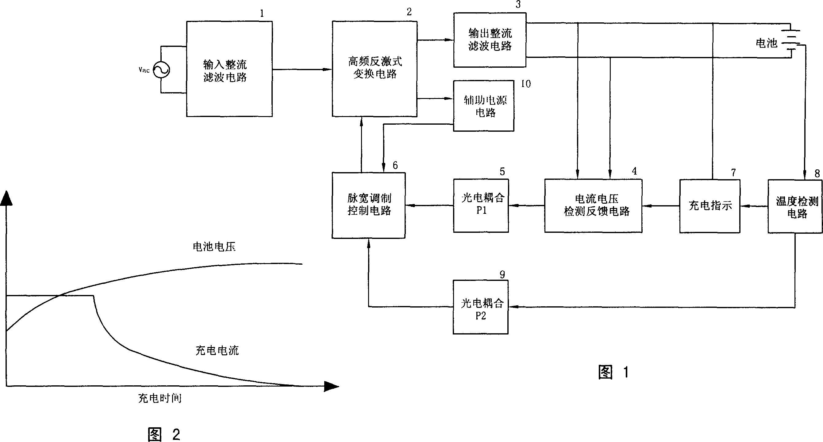
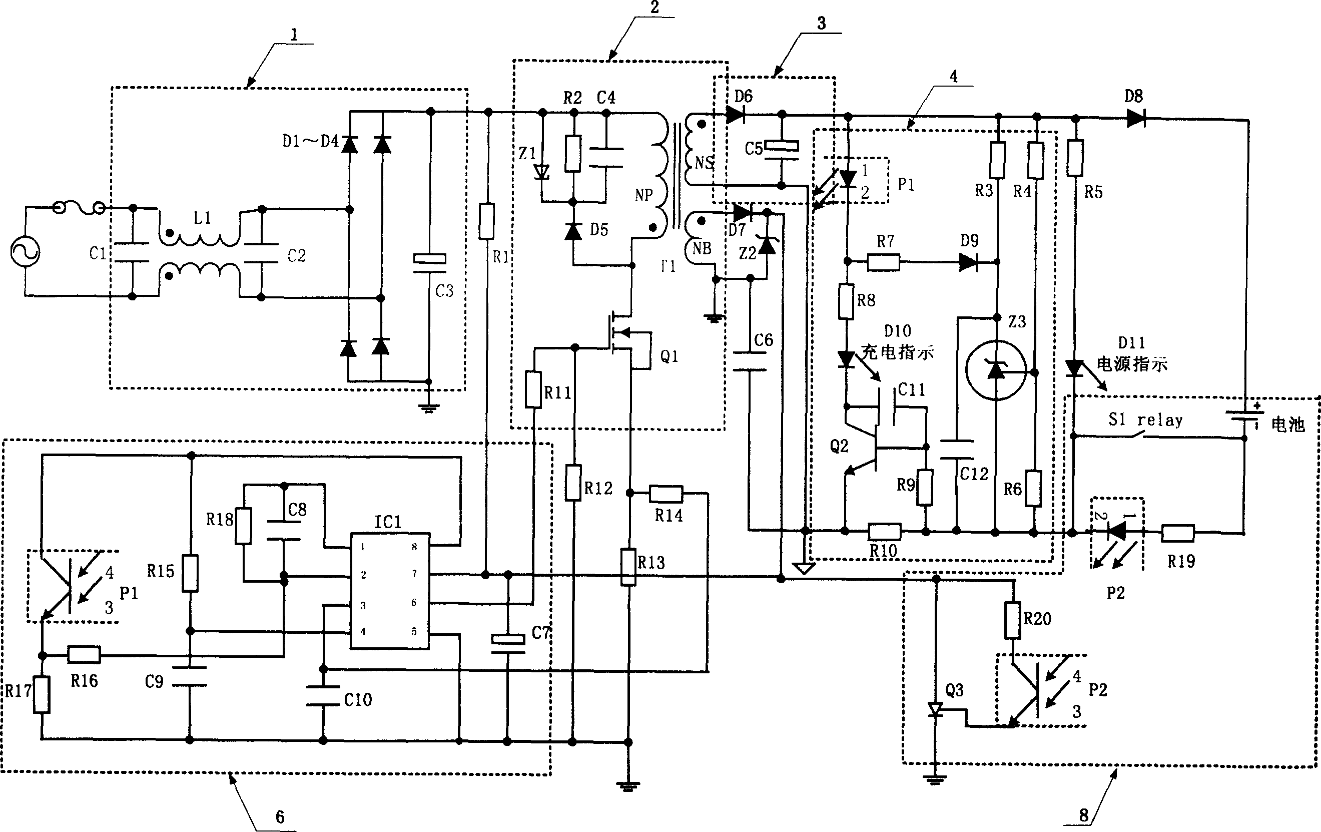
[0010] Figure 1 is a circuit block diagram, including input rectification and filtering circuit 1, high frequency flyback conversion circuit 2, output rectification and filtering circuit 3, current and voltage detection feedback circuit 4, photoelectric coupling P1 circuit 5, pulse width modulation control circuit 6, photoelectric coupling P2 circuit 9 and auxiliary power supply 10 . The photoelectric coupling circuit 5 inputs the given signal of the current and voltage detection feedback circuit 4 into the pulse width modulation control circuit 6 to feed back the output duty cycle. The temperature detection and protection circuit is composed of a battery temperature detection circuit 8, a photoelectric coupling circuit P2, and a pulse width modulation control circuit 6. The photoelectric coupling P2 is connected to the output terminal of the battery temperature detection ...


PUM


Abstract

The invention relates to a battery charger, comprising an input rectifier filter circuit, a high frequency inverse-excited converter circuit, an output rectifier filter circuit, an auxiliary power circuit, and a temperature detection-control circuit. It is characterized in that a constant-current stable-voltage control circuit which is formed by a current voltage detect-feedback circuit, an photoelectric coupled circuit, and a impulse-width modulation control circuit in the cascade connection; The rectifier filter circuit transfers the incoming alternating current into direct current, and via the high frequency inverse-excited converter circuit, to separate and output direct voltage to charge the battery; the constant-current stable-voltage control circuit and the impulse-width modulation control chip are combined to control the constant-current charging and the stable-voltage protection; the temperature detection-control circuit is used for temperature protection of battery to avoid overcharge. Said invention has the advantages of high property, lower cost, safety and reliability, while it can be used to charging variable nickel-cadmium battery, nickel-hydrogen battery and lithium battery.

Description

technical field [0001] The invention relates to a charger, in particular to a battery charger with constant current and voltage stabilization. Background technique [0002] There are many deficiencies in current battery chargers. For example, battery chargers for mobile phones have problems such as long charging time, poor versatility, inconvenient portability, and poor safety and reliability. Other electric tools or electric vehicle chargers also have problems such as long charging time, short discharging time, and short battery life. A technical problem, generally starting from the charging method and control method. There are two charging methods: linear and switch. The linear amplification method makes the main switch of the charger work in the linear region, realizes constant current charging, and can prolong battery life, but the linear electric efficiency is low. , The charging time is long, and it cannot meet the requirements of a wide voltage range. The switching ...

Claims


Application Information

Patent Timeline
Patent Type & Authority Applications(China)
IPC IPC(8): H02J7/04G05F1/46
Inventor 陈国成朱士海谢旭明
Owner 陈国成
Why Eureka
Try Eureka