Battery charging circuit and method for charging battery

A battery charging and charging circuit technology, applied in secondary battery charging/discharging, battery circuit devices, circuit devices, etc., can solve problems such as complex costs

Active Publication Date: 2008-08-06
CHENGDU MONOLITHIC POWER SYST
View PDF2 Cites 13 Cited by
  • Summary
  • Abstract
  • Description
  • Claims
  • Application Information

AI Technical Summary

Problems solved by technology

But some of these methods proved to be too complicated or too expensive

Method used


Image

  • Battery charging circuit and method for charging battery

Examples


Embodiment Construction

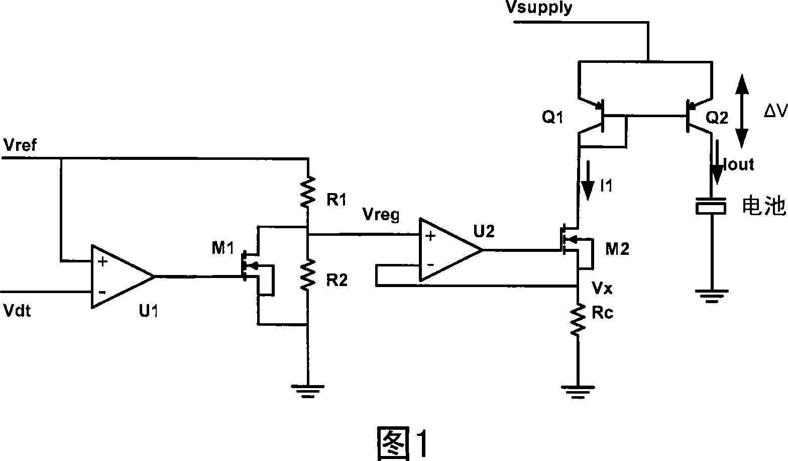
[0011] The purpose of the present invention is to monitor the temperature of the charging IC. When the temperature of the charging IC exceeds a certain predetermined temperature value, the circuit of the present invention will reduce the temperature of the IC. Embodiments will be specifically described below.

[0012] As shown in FIG. 1 , a temperature sensor (not shown) detects the temperature of the charging chip and provides a voltage signal Vdt to the inverting input terminal of the comparator U1. The voltage signal Vdt can also be obtained by a temperature sensor (not shown) that directly monitors the temperature of the IC. The non-inverting input terminal of the comparator U1 is connected to the reference voltage Vref and one terminal of the resistor R1, and the other terminal of the resistor R1 is connected to the resistor R2 and the drain of the metal oxide semiconductor field effect transistor (Metal Oxide Semiconductor Field Effect Transistor, MOSFET) M1 and the no...


PUM


Abstract

The invention provides a battery charger circuit and a method for battery charge. The battery charging circuit monitors a charging die temperature, or directly monitor IC temperature using a temperature sensor. A maximum temperature allowed for the charging die is predetermined. The charging circuit is capable of reducing charging current at the predetermined maximum temperature value. The charging die signal is compared by a reference signal to achieve the reduction of charging current at the maximum allowed temperature value. The battery charge circuit includes: a charge current loop for providing charge current to battery, therein, said charge current changes according with adjusted voltage; a control loop which can adjust said adjusted voltage according with charging die temperature adjustment; and when said charging die temperature exceeds to pre-set temperature threshold, said control loop can reduce said charging current by reducing said adjusted voltage. The battery charger circuit and method can realize high-efficiency charging and overheat protection with high-efficiency and low-cost.

Description

technical field [0001] The present invention relates to a battery charger, in particular to a battery charger circuit capable of monitoring and adjusting the temperature of a charging chip during battery charging so as to prevent an integrated circuit (IC) from overheating and a method for charging the battery. Background technique [0002] Normally, the temperature of the IC rises when charging the battery. This heat during charging is caused by IC power dissipation, mainly by the charging current. When the charging current is reduced, the heat is usually reduced as well. There have been various attempts in the industry over the years to achieve efficient charging and prevent overheating at the same time by controlling the charging current to an optimal value. But some of these methods proved either too complicated or too expensive. Because most rechargeable batteries are used in consumer electronics, the cost of charging ICs is the main consideration for manufacturers o...

Claims


Application Information

Patent Timeline
Patent Type & Authority Applications(China)
IPC IPC(8): H02J7/00H01M10/44
CPCH01M10/44Y02E60/10H02J7/007192Y02B40/00Y02E60/13
Inventor 张正伟
Owner CHENGDU MONOLITHIC POWER SYST
Why Eureka
Try Eureka