RFID multiple range method and system

Inactive Publication Date: 2006-02-16
MRID UK
View PDF10 Cites 28 Cited by
  • Summary
  • Abstract
  • Description
  • Claims
  • Application Information

AI Technical Summary

Benefits of technology

[0014] In another embodiment, the receiver is used to determine the location of the RFID tag so that telephone calls can be forwarded to a specific employee wearing a badge with a RFID tag without paging the entire building.
[0015] In another embodiment of the present invention, a receiver has two (2) sensitivities, such as “near” and “far” to describe the distance of the RFID tag from a receiver. Accordingly, the receiver categorizes an RF signal as “near” or “far” based on the power of the RF signal received. Thus, for example, when an object with an RFID tag is relocated from one monitored room to another, the RFID receiver in the previous room will determine that the object is “far” based on the weakness of the RF signal. The receiver in the room now occupied by the object with the RFID tag detects and identifies the tag as “near” based on the strong RF signal. In this way, the receiver can determine the presence of an RFID tag in its vicinity, and distance of an RFID tag to the receiver.
[0016] In another embodiment of the invention, a predetermined set of surgical tools required for a particular surgical procedure is gathered together on a cart and transported to an operating room. An information processor (e.g., a handheld computer) and RFID receiver are also present on the cart. Each of the tools to be used in the procedure has an attached RFID tag. The information processor contains an electronically stored index of the tools required to be present for the particular surgical procedure, and alerts the user if any necessary tool is missing prior to transporting the cart, i.e., mobile platform, to the operating room. During the surgical procedure, the information processor monitors the use of the tools. When the procedure is completed, the information processor alerts the user if any surgical tool has not been returned to the cart. In this manner, the system ensures that all required tools are present prior to beginning the surgery, and prevents mistakes such as inadvertently leaving a surgical tool in a patient after the surgical procedure.
[0021] In another embodiment of the invention, a plurality of RFID receivers on the mobile platform are each interconnected with a single information processor. In this way the location of various tools on the mobile platform may be grouped together or divided into a number of zones for easier location of specific tools. One or more of these RFID receivers may be removable from the mobile platform in order to maintain inventory information on tools that are temporarily in use at a remote destination from the mobile platform.
[0025] The specific embodiments described above provide a fully automated method and system for managing objects and determining the locations of object from a predetermined origin in an economical manner. A primary object of the invention is to provide immediate feedback to the user of the mobile platform as to the availability of all necessary tools to carry out the proposed task, and the presence of all tools at the completion of the task prior to returning from the remote destination. Thereby the possibility for error or loss is minimized.
[0027] Still another important object is to provide a system and method can operate in conjunction with a system wide information processor and can manage and monitor all tools used by a number of distinct mobile platforms. By using the invention, mobile platforms will arrive at the remote destination with the full set of tools required to carry out the task or function and tool losses will be greatly reduced.

Problems solved by technology

Upon arrival at the remote destination, missing objects such as critical tools can cause severe problems in performing the necessary task.
In addition, without an adequate method and system to monitor the objects, the mobile platform may return to its origination point without all the tools or objects of concern.
For mobile locations carrying hundreds of objects, this operation is time-consuming.
In addition, missing tools are not identified until the mobile platform has returned from a remote site.
However, the prior art RFID systems do not have the ability to provide a management system that allows a user to monitor the tools at a remote destination or to automatically alert a user when tools are missing or to determine the specific location of an object from an origin.

Method used


Image

  • RFID multiple range method and system
  • RFID multiple range method and system
  • RFID multiple range method and system

Examples


Embodiment Construction

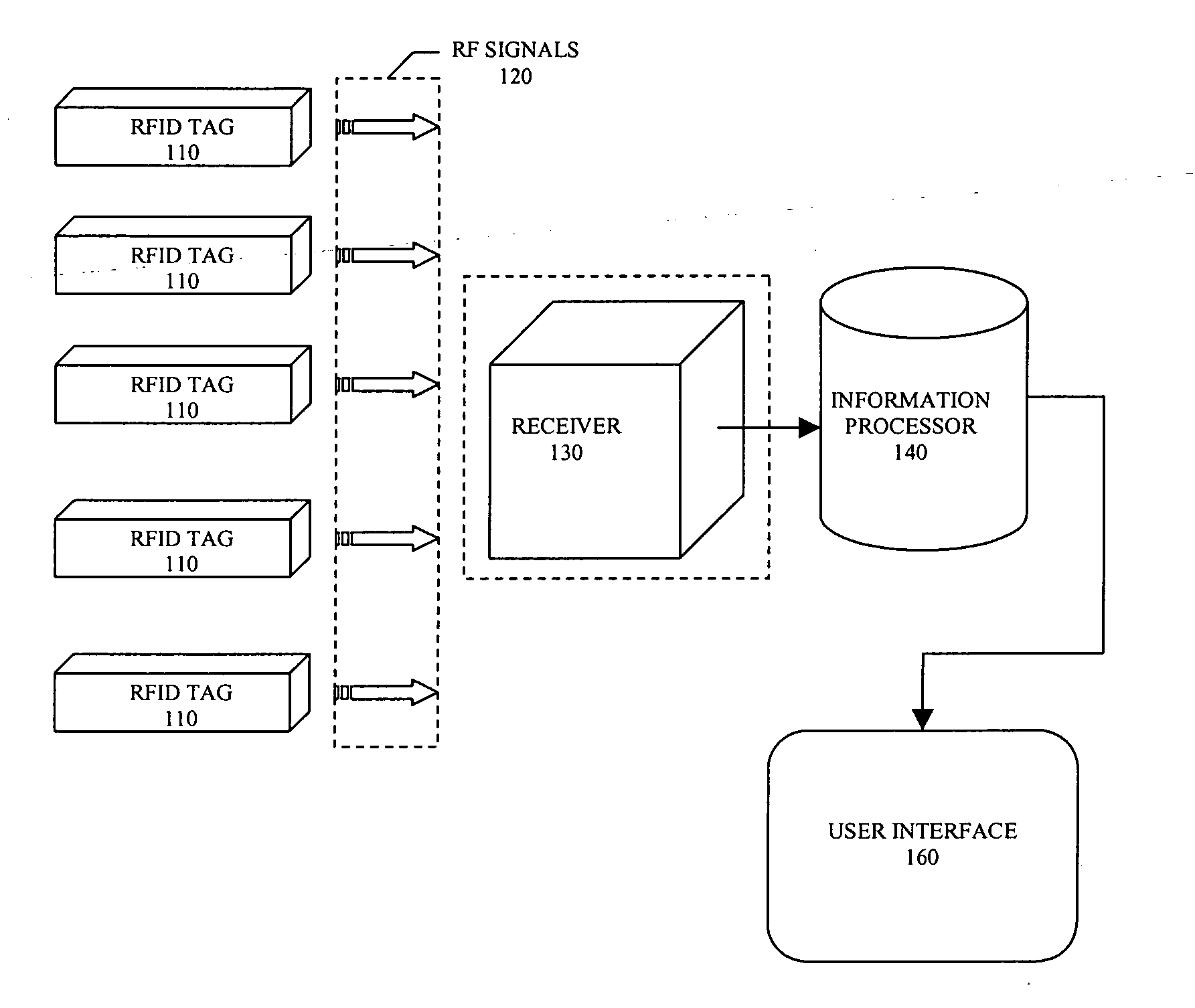
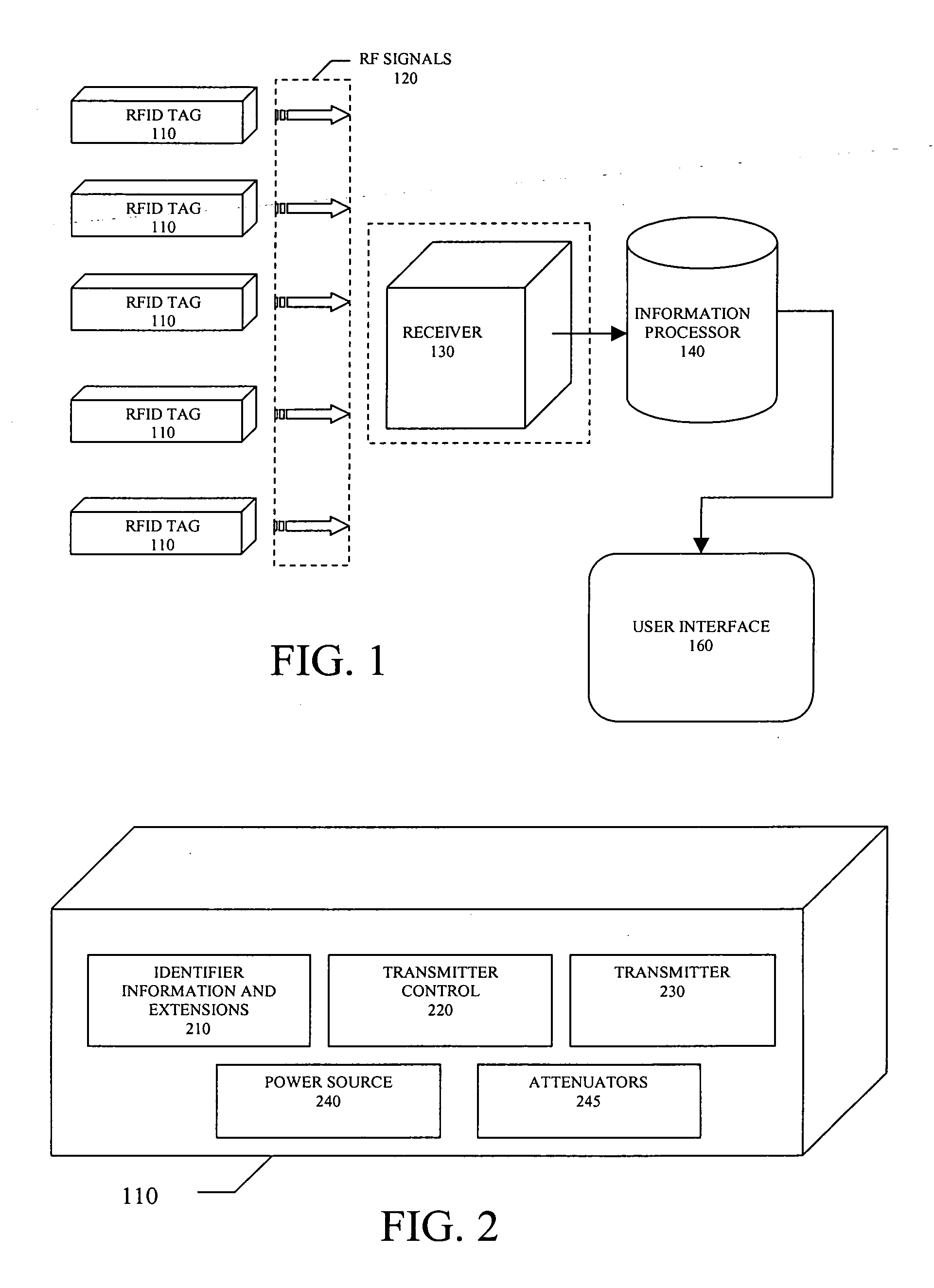
[0034] Referring to FIG. 1, in one embodiment of the invention each RFID multiple range tag 110 is attached in a semi-permanent manner to the desired object. The identifier information of the RFID tag 110 and an index regarding the object to which the tag is attached is provided in a database electronically stored on the information processor 140. The RFID tags 110 that are attached to the desired objects transmit their identifier information using RF signals 120 to a receiver 130 at an origin location.

[0035] The receiver 130 is interconnected to the information processor 140. In this manner the information processor 140 is continually and automatically monitoring the identifier information of all of the RFID tags 110 that are within RF reception range of the receiver 130 located at an origin. The information processor 140 analyzes and determines the spatial location of each RFID tag 100 from the receiver 130 based on the RF signals 120 received.

[0036] Using the information collec...


PUM


Abstract

The present invention is a method and system for determining the range of an RFID tag from an origin using radio-frequency identification (“RFID”) tags. An RFID tag with a unique numerical identifier is secured to an object. The RFID tag transmits its unique numerical identifier using RF signals, wherein the numerical identifier further comprises an array of extensions. The strength of each of the RF signals corresponds to an extension of the array of extensions. A receiver reads the RF signals and determines the unique numerical identifier and extensions being transmitted. An information processor interconnected with the receiver analyzes the unique numerical identifier and extensions from a predetermined index, and the information processor determines the range of the identity and range of the RFID tag from an origin.

Description

CROSS-REFERENCE TO RELATED APPLICATIONS [0001] This application claims the benefit of U.S. Provisional Application No. 60 / 588,033 filed Jul. 13, 2004. The disclosure of the provisional application is incorporated herein by reference.BACKGROUND OF THE INVENTION [0002] 1. Field of the Invention [0003] The present invention relates to radio frequency identification, and more specifically to a method and system using radio frequency identification tags to determine the specific location of an object from an origin. [0004] 2. Description of the Prior Art [0005] Object management applications exist in which objects of concern are tracked by a company or group. Examples of such objects of concern include the tools carried on fire engines, the fire engine itself and the firefighter. The objects are typically grouped together into a set depending on the task at hand. [0006] Often times a mobile platform is used for storing and transporting objects of concern. For example, a cart for surgical...

Claims


Application Information

Patent Timeline
IPC IPC(8): G08B13/14
CPCG08B21/0227G08B21/24G08B21/0275
Inventor HINES, TONYHILL, STEVENLUSK, DENNIS
Owner MRID UK
Why Eureka
Try Eureka