
Adjustable bounding box for transparent scanner

Inactive Publication Date: 2006-02-16
PALO ALTO RES CENT INC
View PDF14 Cites 1 Cited by
  • Summary
  • Abstract
  • Description
  • Claims
  • Application Information

AI Technical Summary

Benefits of technology

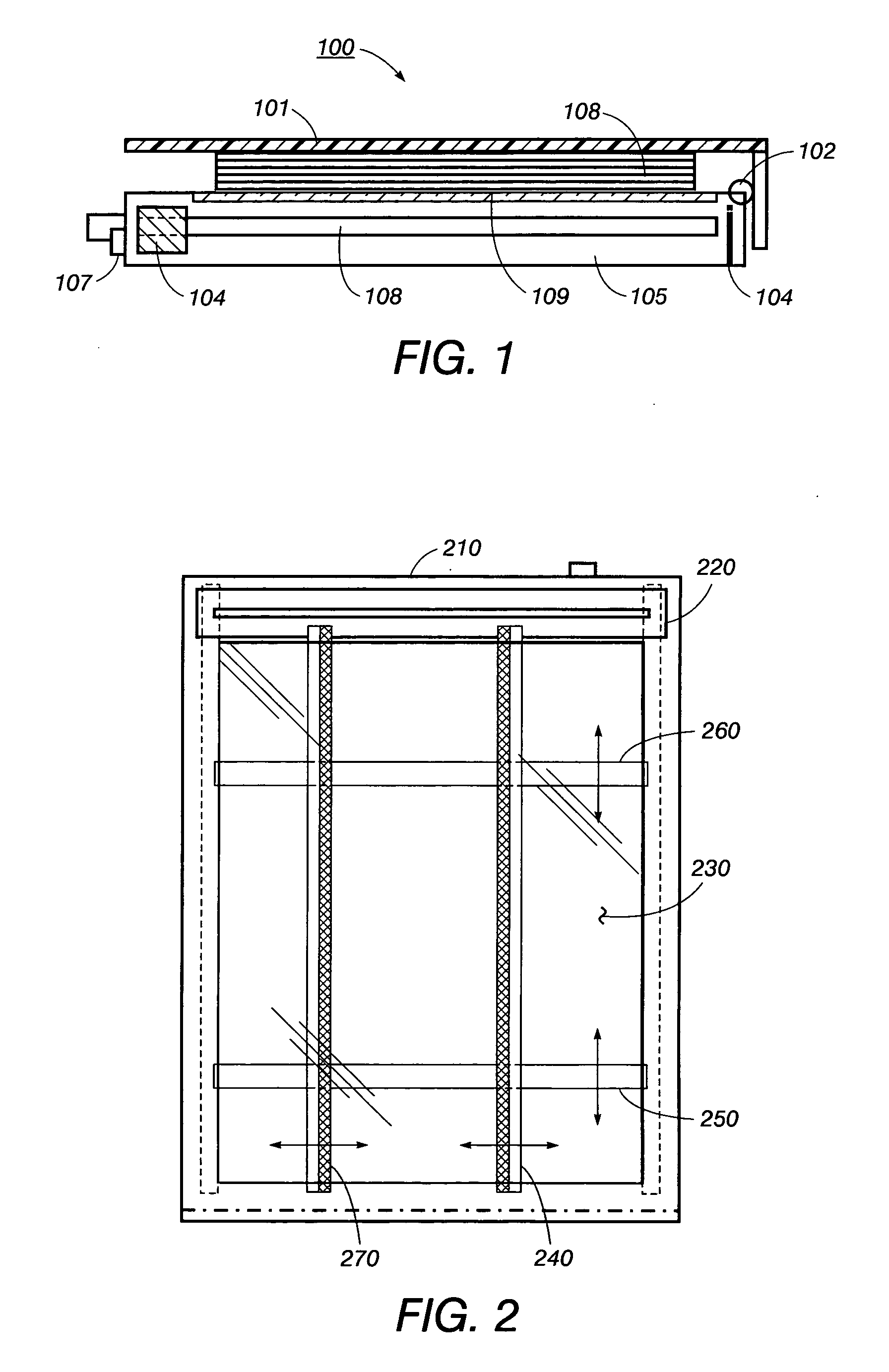
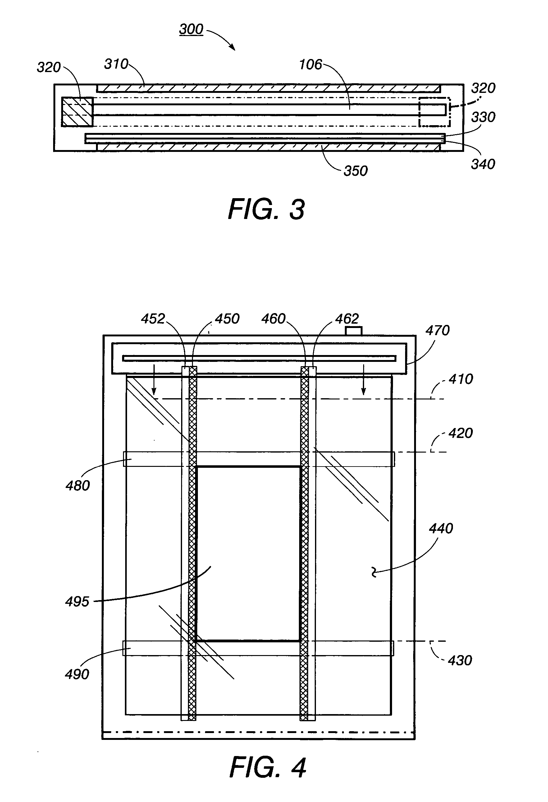
[0005] The disclosed embodiments provide examples of improved solutions to the problems noted in the above Background discussion and the art cited therein. There is shown in these examples an improved apparatus capable of modification of an image prior to scanning by a scanning device having a scanning element, a viewing surface, a glass platen, and a controller having memory capability, includes opaque adjustable bounding strips. The b

Problems solved by technology

However, a typical flatbed scanner may be inconvenient for such tasks as scanning pages of a thick book, whose thickness results in the scanner cover being only partially closed, resulting in an image with undesirable artifacts.
Additionally, because the image is scanned face down, the user is unable to project in advance what a resultant image will be until the image is actually generated.
For example, if the user desires to reproduce only a portion of an image, there is no convenient way for the user to align the scanning document properly prior to scanning.
Or if a user wants to superimpose the image of one document onto that of another document in a precise location, alignment of each document is difficult, since both are face down on the image platen of the scanner.
While overhead scanners of various types have been introduced to scan documents, particularly books, in a face-up position, the size and weight of these overhead scanners render them undesirable for the average consumer.
Although such transparent scanners provide more flexible scanning capability, they do not resolve the problem of selecting a rectangular section from a scanned original.

Method used


Image

  • Adjustable bounding box for transparent scanner
  • Adjustable bounding box for transparent scanner
  • Adjustable bounding box for transparent scanner

Examples


Embodiment Construction

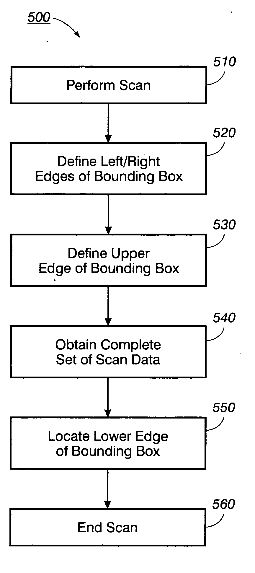
[0014] The adjustable bounding box described herein a user may change originals, crop the boundaries of each selection, and issue a scan command, all as a single streamlined task at a transparent scanner. Final image files are all cropped to individual desired boundaries without further editing. Because the scanner element only travels once for each original, since a preview scan is eliminated, there is a fifty percent reduction in mechanical wear to the scanner.

[0015] The bounding box integrates a set of strips in the scanner that a user can manually adjust to form a rectangular bounding box over an original document to crop the document to the portion desired by the user. Together with a start button on the scanner's body, a user can change originals, crop the boundaries of each selection, and issue a scan command, all as one streamlined task at the scanner. Thus the user's time is conserved by elimination of waiting for a preview scan and enlarging and fine-tuning the bounding b...


PUM


Abstract

An apparatus capable of modification of an image prior to scanning by a scanning device having a scanning element, a viewing surface, a glass platen, and a controller having memory capability, includes opaque adjustable bounding strips. The bounding strips are viewable through the viewing surface of the scanning device and are located between the inside surface of the glass platen and the scanning element. The bounding strips are movable to identify a selected portion of an image to be scanned. The apparatus also includes software for performing a scan of the selected portion of the image and identifying its location, based on the location of the adjustable bounding strips.

Description

INCORPORATION BY REFERENCE [0001] The following U.S. patents are fully incorporated herein by reference: U.S. Pat. No. 6,271,939 (“Transparent and Flatbed Scanner”); U.S. Pat. No. 6,470,099 (“Scanner with Multiple Reference Marks”); and U.S. Pat. No. 6,661,539 (“Vertically Oriented Document Scanner”).BACKGROUND [0002] This disclosure relates generally to transparent flatbed scanning systems and more particularly relates to a method and system to modify image placement, size, and composition through use of an adjustable bounding box. [0003] Scanning systems are typically utilized to convert paper-based objects, such as texts and graphics to an electronic format which can be analyzed, distributed, and archived. However, a typical flatbed scanner may be inconvenient for such tasks as scanning pages of a thick book, whose thickness results in the scanner cover being only partially closed, resulting in an image with undesirable artifacts. Additionally, because the image is scanned face d...

Claims


Application Information

Patent Timeline
IPC IPC(8): H04N1/04
CPCH04N1/00018H04N1/00068H04N1/00082H04N1/00092H04N2201/0434H04N1/193H04N2201/0416H04N2201/0426H04N2201/043H04N1/1017
Inventor CHEUNG, PATRICK C.
Owner PALO ALTO RES CENT INC
Learn More