Network system and supervisory server control method

Inactive Publication Date: 2006-02-16
FUJITSU LTD
View PDF5 Cites 45 Cited by
  • Summary
  • Abstract
  • Description
  • Claims
  • Application Information

AI Technical Summary

Benefits of technology

[0013] In view of the foregoing, it is an object of the present invention to provide a network system which facilitates the task of replacing switches pertaining

Problems solved by technology

Further, ping-based methods are not a preferable option for several reasons.
Second, ping commands impose some amounts of extra traffic load and processing burden on t

Method used


Image

  • Network system and supervisory server control method
  • Network system and supervisory server control method
  • Network system and supervisory server control method

Examples


first embodiment

[0042] This section describes a first embodiment of the invention, in which a switch that has detected a link-down event in its own port forcibly disables other port links so as to propagate the link-down state to other switches belonging to the same switch group.

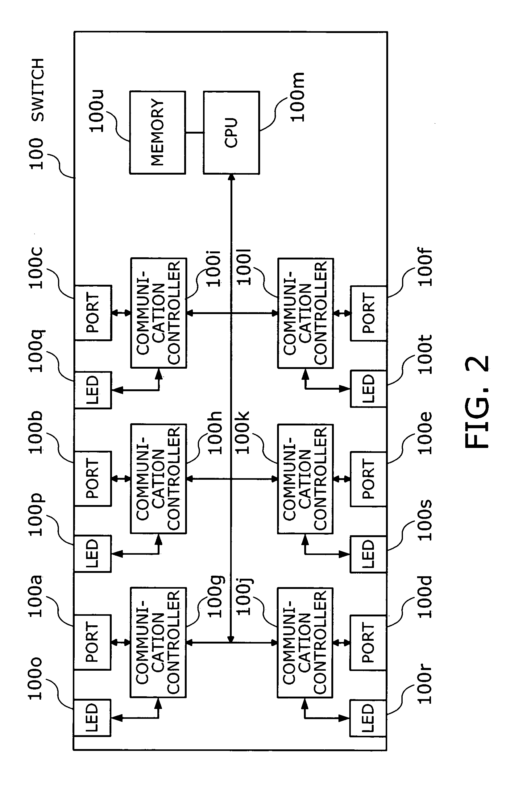
[0043]FIG. 2 is a conceptual view of a switch. This switch 100 has the following elements: ports 100a, 100b, 100c, 100d, 100e, and 100f; communication controllers 100g, 100h, 100i, 100j, 100k, and 1001; a central processing unit (CPU) 100m; light-emitting diode (LED) indicators 100o, 100p, 100q, 100r, 100s, and 100t; and a memory 100u.

[0044] The ports 100a to 100f are interface points where the switch 100 receives incoming electronic signals and transmit outgoing electronic signals under prescribed conditions. The communication controllers 100g to 100l control data flow inside the switch 100. Specifically, they inform the CPU 100m of a link-down event that has occurred at their corresponding ports in active use. They also...

second embodiment

[0068] This section describes a second embodiment of the present invention, in which switches 100 are configured to disable a limited number of ports, rather than all ports, when they detects a link-down event. Specifically, ports on each switch 100 is divided into a plurality of groups. When one port goes down, the link-down state propagates to other ports that belong to the same group as the failed port. The membership of each port group is defined previously in a port group management table on the memory 100u.

[0069]FIG. 8 shows an example of a port group management table. This port group management table 500 describes groups of ports on a switch 100, including state of each group. To serve as part of a network system, the switch 100 enables or disables port groups according to the table 500.

[0070] The illustrated port group management table 500 has the following data fields: “Group Number,”“Member Port Number,”“Group State,” and “Member Port State.” The group number field conta...

third embodiment

[0099] This section describes a third embodiment which employs a supervisory server. Switches 100 have the functions of notifying the supervisory server of a link-down event that they have detected. In response to the problem notification, the supervisory server commands the switches 100 to disable a predetermined set of ports.

[0100] The use of a separate supervisory server to control switch ports enables the port groups to be defined across a plurality of switches 100. The following example assumes three port groups defined across three switches 100 each having twelve ports.

[0101]FIG. 12 shows a system where a supervisory server is deployed to detect a problem in the network. Specifically, the system includes switches 401, 402, and 403, a supervisory LAN 404, a supervisory server 405, a monitor 406, a multiple switch port group database 700, and an intra-group position database 800. The switches 401 to 403 have basically the same hardware configuration as that described in FIG. 2...


PUM


Abstract

A network system which facilitates the task of replacing switches pertaining to a detected link failure. A server network is formed from a plurality of switches and links. The link state of each port on the switches is being monitored by a link-down detector, and a switch port that has entered a link-down state from a link-up state is identified as an inoperative port. Upon detection of such a link-down event, a function disabler disables link functions of specified ports of other switches in the switch group to which the switch having the inoperative port belongs, so that the servers on the network will change their setups all at once and continue the communication through new paths.

Description

CROSS-REFERENCE TO RELATED APPLICATIONS [0001] This application is based upon and claims the benefits of priority from the prior Japanese Patent Application No. 2004-236279, filed on Aug. 16, 2004, the entire contents of which are incorporated herein by reference. BACKGROUND OF THE INVENTION [0002] 1. Field of the Invention [0003] The present invention relates to a fault tolerant network system and a method for controlling a supervisory server therefor. More particularly, the present invention relates to a network system, as well as a supervisory server control method therefor, which detects a problem with a switch port and disables functions of one or more other ports. [0004] 2. Description of the Related Art [0005] Redundancy has been widely used to realize fault tolerant networks. FIG. 18 shows an example of a conventional network with a dual redundant design. Specifically, the illustrated network is formed from one group of switches 911, 912, and 913 (shown on the left), another...

Claims


Application Information

Patent Timeline
IPC IPC(8): H04J3/14H04J1/16H04L1/00H04L12/26H04L12/28H04L12/56H04L45/58H04L45/586
CPCH04L1/22H04L41/0213H04Q3/0075H04L49/557H04L43/0811
Inventor NOGUCHI, YASUOTAKE, RIICHIROTAMURA, MASAHISATSUCHIYA, YOSHIHIROOGIWARA, KAZUTAKAEJIRI, ARATAMARUYAMA, TETSUTAROKAMOSHIDA, MINORU
Owner FUJITSU LTD
Why Eureka
Try Eureka