Light coupling structures for optical touch panels
a technology of optical touch panel and light coupling structure, which is applied in the direction of planar/plate-like light guide, mechanical equipment, instruments, etc., can solve the problems of difficult and/or costly optical access to edge surfaces, unsatisfactory attachment of light sources, and difficulty in optically accessing edge surfaces. achieve uniform touch sensitivity
- Summary
- Abstract
- Description
- Claims
- Application Information
AI Technical Summary
Benefits of technology
Problems solved by technology
Method used
Image
Examples
first embodiment
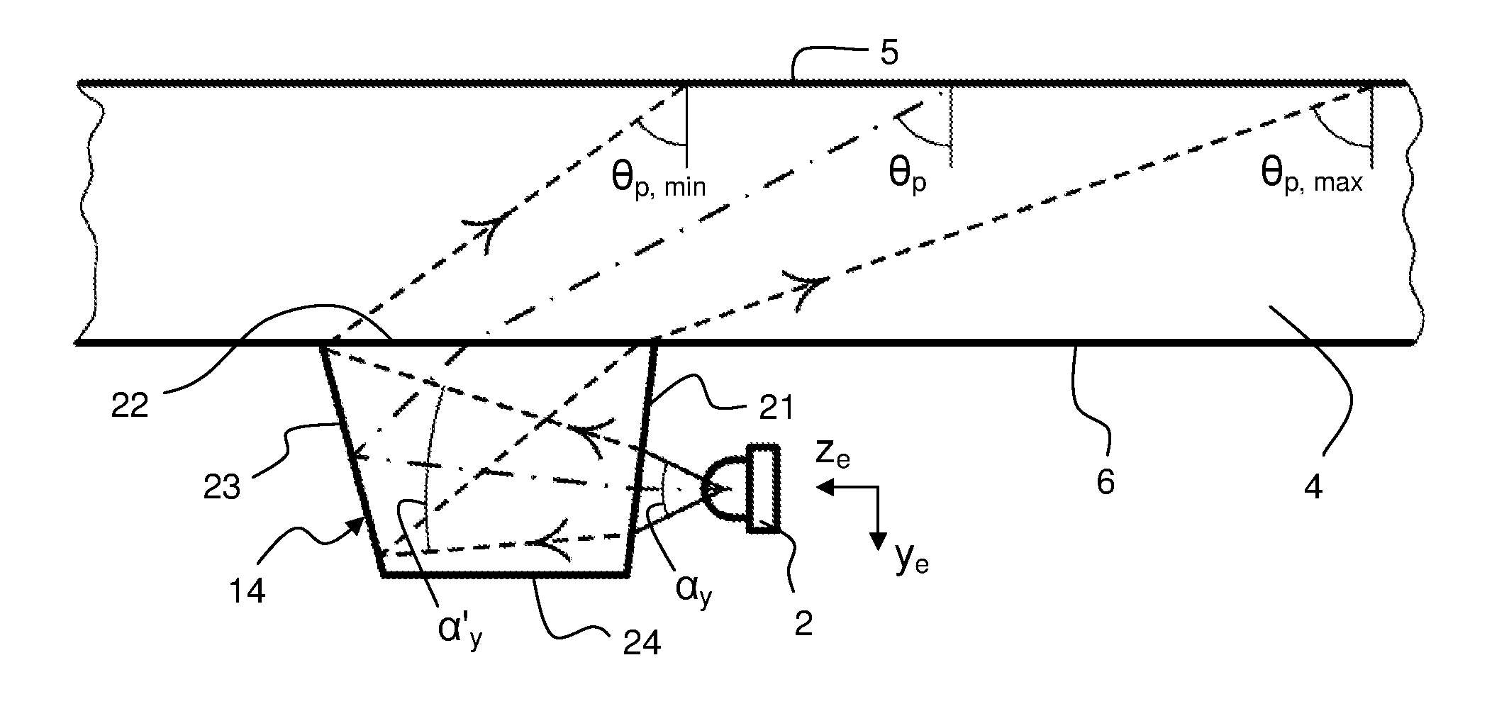
[0096]FIG. 6 is a perspective view of the incoupling element 14 as attached to the bottom boundary surface 6 of the panel 4, e.g. by means of an optical adhesive. The incoupling element 14 is made of an optically transparent material and comprises a planar light entry face 21 arranged to project from the panel 4, a planar light exit face or attachment surface 22 arranged to face and be affixed to the boundary surface 6, and a three-dimensional control surface 23 which is designed with respect to the solid angle Ω (FIG. 3) of the emitter 2 so as to achieve the desired panel divergence φp, main direction zp and bounce angle θp of the injected light. A coordinate system is defined at the center of the exit face, with zc extending normal to the exit face, and xc extending parallel to the main direction (zp) of the light coupled into the panel 4.
[0097]FIG. 7 is a top plan view of the first embodiment as attached to the panel 4 and combined with an emitter 2. FIG. 7 illustrate defining li...
second embodiment
[0114]FIGS. 14A-14B are elevated side views, taken from mutually orthogonal sides, of an incoupling element 14 according to a The incoupling element 14, which is attached to the bottom boundary surface 6 of the panel 4, is designed as an elongate light guide of light transmissive material that defines an entry face 21 at one end and an exit face 22 at the other end. The light guide 14 comprises a first pair of elongate opposing control surfaces 30, 31 that expand the emitter divergence αx into a component divergence φc at the exit face 22, resulting in a desired panel divergence φp inside the panel 4. As shown in FIG. 14A, the control surfaces 30, 31 taper from the entry face 21 to the exit face 22, as seen in a first geometric plane which extends along the light guide 14 and coincides with the xe-ze-plane of the emitter. Thereby, the reflection angle of the light propagating between the control surfaces 30, 31 is decreased for every reflection inside the light guide 14, whereby th...
PUM
 Abstract
Description
Claims
Application Information
 - R&D
- Intellectual Property
- Life Sciences
- Materials
- Tech Scout
- Unparalleled Data Quality
- Higher Quality Content
- 60% Fewer Hallucinations
Browse by: Latest US Patents, China's latest patents, Technical Efficacy Thesaurus, Application Domain, Technology Topic, Popular Technical Reports.
© 2025 PatSnap. All rights reserved.Legal|Privacy policy|Modern Slavery Act Transparency Statement|Sitemap|About US| Contact US: help@patsnap.com


