Optical beam combiner

a combiner and optical beam technology, applied in the field of optical devices, can solve the problems of the angle of incidence and complicate the coupling of light beams into optical fibers

Inactive Publication Date: 2006-02-16
THE OHIO STATES UNIV
View PDF1 Cites 9 Cited by
  • Summary
  • Abstract
  • Description
  • Claims
  • Application Information

AI Technical Summary

Problems solved by technology

A problem arises at the final or output stage of the White cell cross-connection device where the multiple light beams are ultimately directed from different spatial l

Method used


Image

  • Optical beam combiner
  • Optical beam combiner
  • Optical beam combiner

Examples


Embodiment Construction

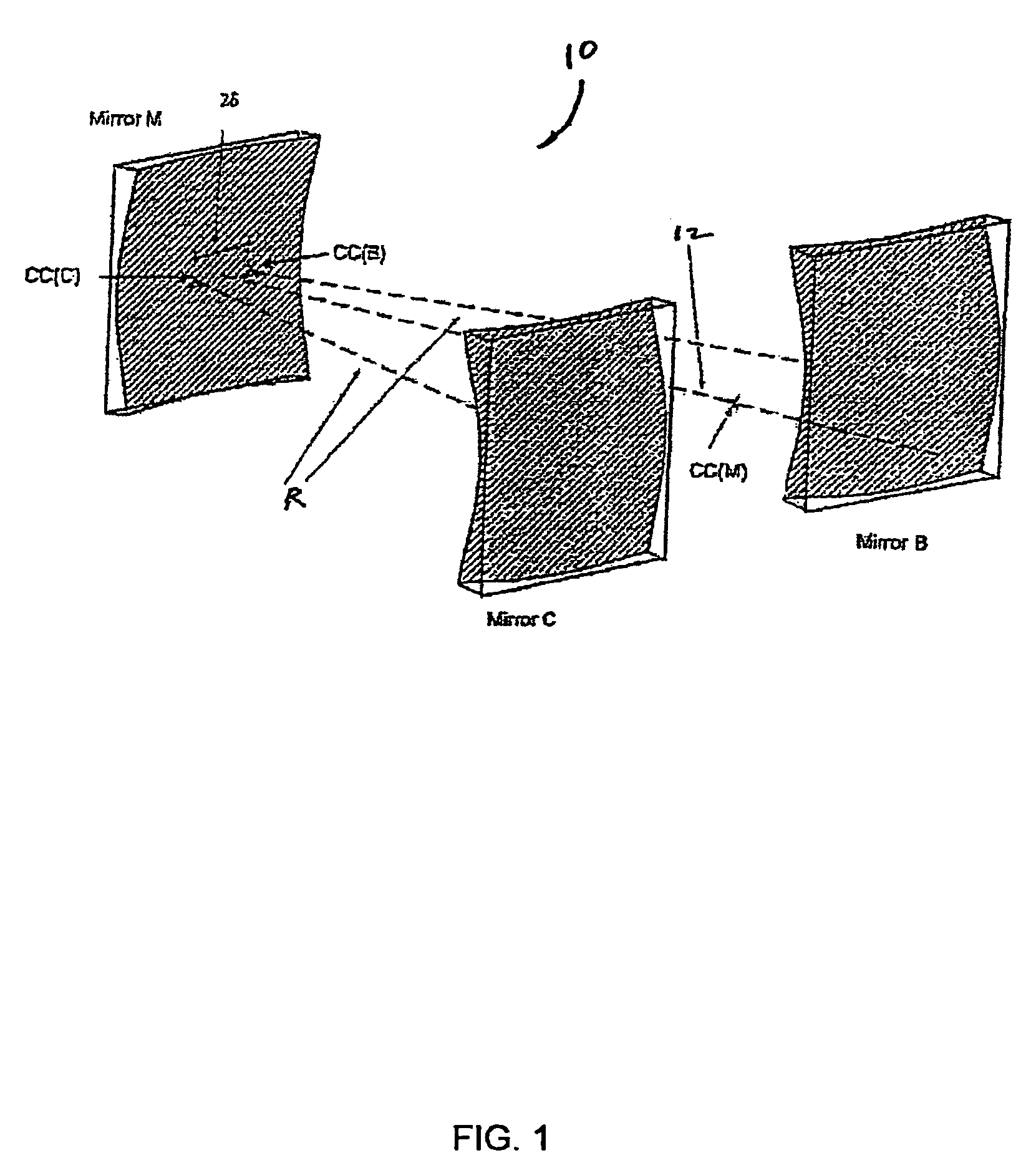
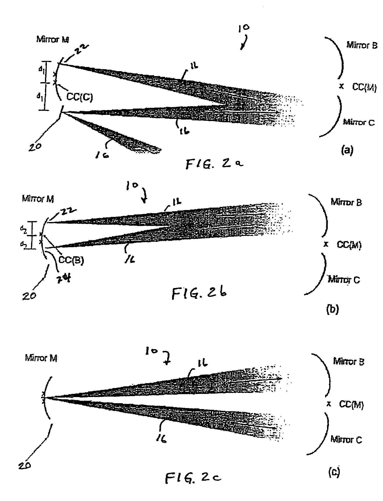
[0021] An optical switch based on the principles of an optical White cell will exemplify an optical cross-connection device for the purposes of describing one or more embodiments of the present invention. The optical White cell is an example of a multi-pass light beam optical system for generating a series of spot illuminations in sequence for an input light beam as will be better understood from the following description. Other examples of multi-pass light beam systems include a Herriot cell or any of the alternative spot pattern generators disclosed in U.S. Pat. No. 6,266,176. For the present example, a White cell comprising a set of three spherical mirrors with identical radii of curvature will be used. The multi-pass system of spherical mirrors will refocus the beam continuously within the White cell. One of the White cell's spherical mirrors may be replaced with an array of micro mirrors which may be made using micro-electromechanical systems (MEMS) techniques and will hereinaf...


PUM


Abstract

An optical beam combiner for combining a plurality of light beams comprises: a plurality of spherical mirrors; and a flat mirror, the plurality of spherical mirrors and the flat mirror configured to form at least one multiple pass light beam optical arrangement for receiving the plurality of light beams and for superimposing spot images of the light beams onto a single location with a single incident angle. In addition, a waveguide-based optical White cell comprises: a waveguide having front and rear edges, the inside surfaces thereof being coated with a reflective material, wherein the front edge including an input section for the passage of at least one light beam into the waveguide; at least one waveguide lens disposed in front of the inside surface of the rear edge to form a plurality of waveguide spherical mirrors at the rear edge; a plurality of angled micro mirrors disposed at the inside surface of the front edge; and the plurality of waveguide spherical mirrors and the coated front edge configured to form at least one waveguide White cell.

Description

[0001] This utility application claims the benefit of the filing date of the U.S. Provisional Application 60 / 588,729, entitled “Optical Beam Combiner”, and filed Jul. 16, 2004.BACKGROUND OF THE INVENTION [0002] The present invention relates to optical devices, in general, and more particularly, to an optical beam combiner for receiving a plurality of light beams and superimposing spot images of the plurality of light beams onto a single location with a single incident angle. [0003] Generally, an optical cross-connection device, like a White cell optical switch, for example, comprises a plurality of optical elements disposed in a predetermined spatial three dimensional pattern for directing one or more light beams from an input through a plurality of reflections to an output. Multiple light beams may bounce through various stages of the device simultaneously. A problem arises at the final or output stage of the White cell cross-connection device where the multiple light beams are ult...

Claims


Application Information

Patent Timeline
IPC IPC(8): G02B6/26
CPCG02B6/0018G02B6/0068G02B19/0033G02B19/0023G02B26/0833
Inventor ANDERSON, BETTY LISEARGUETA-DIAZ, VICTOR
Owner THE OHIO STATES UNIV
Why Eureka
Try Eureka