
Textile fabric structure

a technology of textile fabric and structure, applied in the field of textile fabric structure, can solve the problems of complex control software, unsuitable mass market special solutions, and a great deal of planning for special solutions

Inactive Publication Date: 2006-02-16
INFINEON TECH AG
View PDF6 Cites 103 Cited by
  • Summary
  • Abstract
  • Description
  • Claims
  • Application Information

AI Technical Summary

Problems solved by technology

The special solutions require a great deal of effort on planning, in each case it having to be specified exactly when planning the building at which locations the respective sensors and actuators are to be provided.
A further disadvantage in such a special solution is that each sensor and each actuator is driven individually and is in each case provided separately with power lines and data lines.
Furthermore, according to the prior art, complex control software is required to drive the respective sensors and actuators, which has to be matched to the specific geometry of the respective special solution in order to permit three-dimensional or planar registration of objects, in particular of persons.
Such special solutions are thus unsuitable for the mass market, since they are inflexible and inexpensive.

Method used


Image

  • Textile fabric structure
  • Textile fabric structure
  • Textile fabric structure

Examples


Embodiment Construction

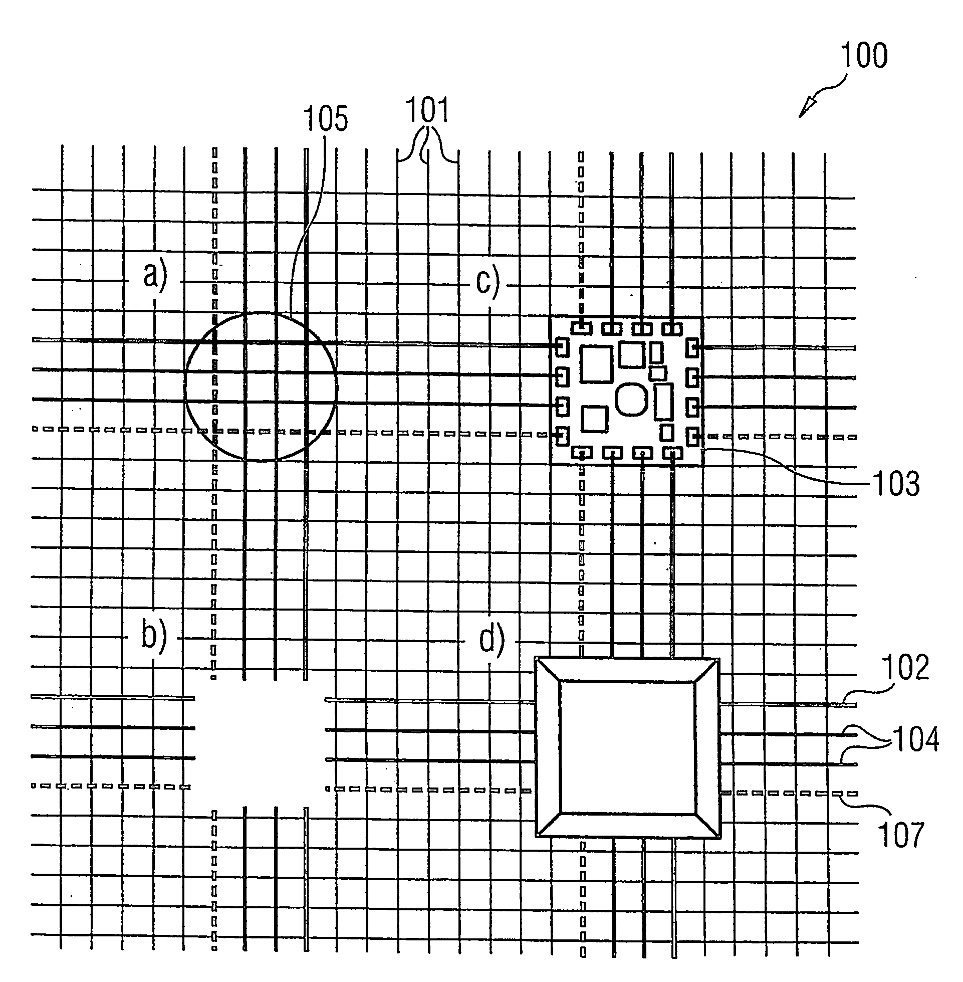
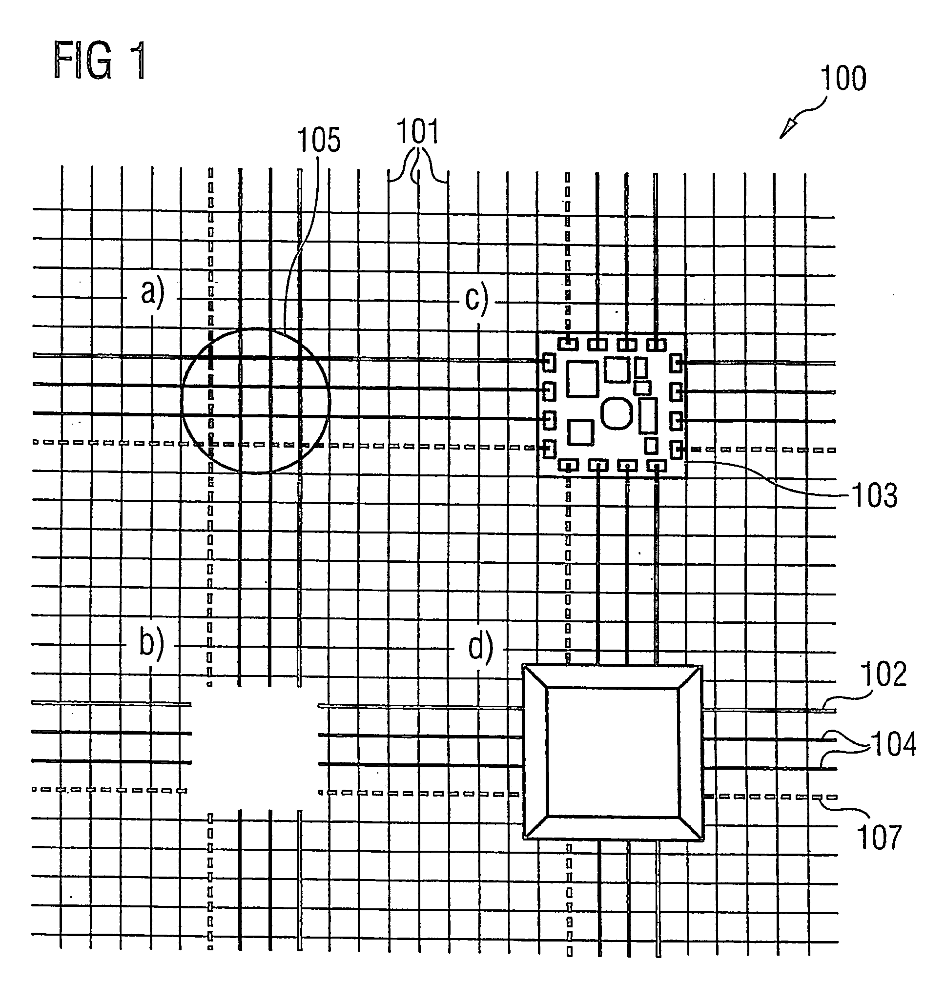
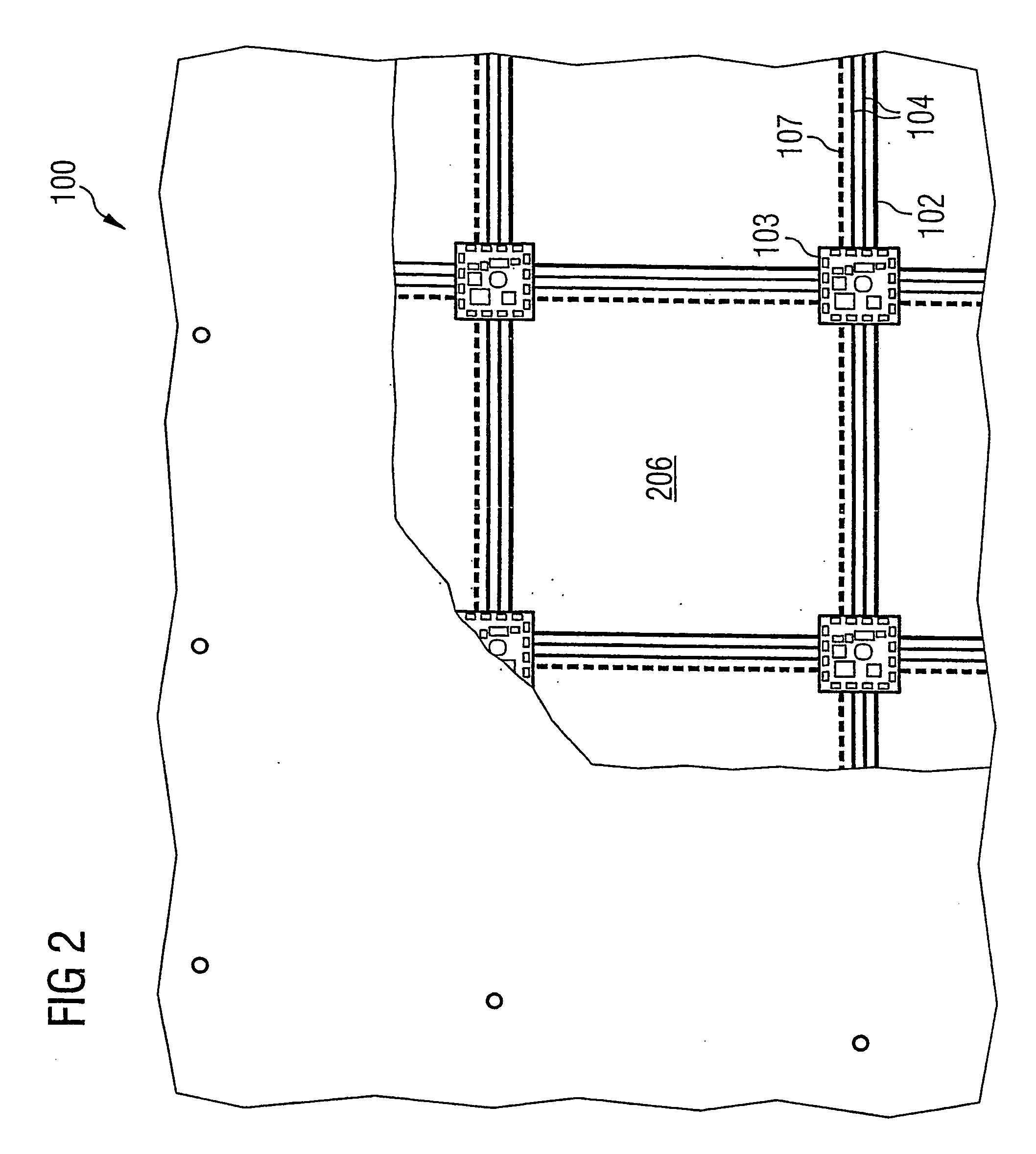
[0020] A textile fabric structure is provided which can be used for covering surfaces, preferably a floor, a wall or a ceiling. The textile fabric structure can be used in any desired textile fabrics, for example including curtains, textile roller blinds or awnings. The textile fabric structure has a plurality of microelectronic components for electronic data processing, which plurality of microelectronic components can be supplied with power via electrically conductive threads likewise provided in the textile fabric structure and which are fed with the data to be processed by means of the data transmission threads or can transmit via the latter. As a result of its construction, the textile fabric structure has the advantage over the prior art that it can be produced with a large area and can be cut simply to any desired shape. Thus, it can be adapted to any desired area on which it is to be laid. It is not necessary to couple the individual microelectronic components, such as LEDs,...


PUM

PropertyMeasurementUnit
fabric structureaaaaaaaaaa
electrically conductiveaaaaaaaaaa
conductiveaaaaaaaaaa

Abstract

A textile fabric structure having a plurality of microelectronic components, which are arranged in the textile fabric structure, electrically conductive threads, which couple the plurality of microelectronic components to one another, conductive data transmission threads, which couple the plurality of microelectronic components to one another, and electrically nonconductive threads. The conductive threads and the conductive data transmission threads at the edge of the textile fabric structure are each provided with an electric interface and a data transmission interface.

Description

CROSS-REFERENCE TO RELATED APPLICATION [0001] This application is a continuation of International Patent Application Serial No. PCT / DE2004 / 000314, filed Feb. 19, 2004, which published in German on Sep. 10, 2004 as WO 2004 / 076731, and is incorporated herein by reference in its entirety. FIELD OF THE INVENTION [0002] The invention relates to a textile fabric structure, a surface covering structure and a method for determining the interspacing of microelectronic elements of the textile fabric structure with respect to at least one reference position. BACKGROUND OF THE INVENTION [0003] In many areas in building installation technology and in many trade fair structures there is a need to lay sensors and actuators, preferably indicating elements, in a simple way in floors, walls or ceilings. In this case, the intention is for floors, walls or ceilings, alternately or in combination, to be able to perceive contact and / or pressure and to react to the existence of contact and / or a pressure w...

Claims


Application Information

Patent Timeline
Patent Type & Authority Applications(United States)
IPC IPC(8): H02G3/04D03D15/00D02G3/44
CPCD02G3/441D03D1/0088D03D15/00D03D15/0066D03D15/02H05K1/038D10B2101/20D10B2401/16D10B2401/20D10B2503/04D10B2101/12H05K1/0274H05K3/284H05K2201/0281Y10T442/3976Y10T442/30D03D15/258D03D15/67D03D15/547
Inventor GLASER, RUPERT HERMANN JOSEFJUNG, STEFANLAUTERBACH, CHRISTL
Owner INFINEON TECH AG
Learn More