System and method for treating glaucoma

a technology of glaucoma and intraocular pressure, applied in the field of eye intraocular pressure, can solve problems such as damage to the optic nerve, and achieve the effect of reducing the for

Inactive Publication Date: 2006-02-16
BECTON DICKINSON & CO
View PDF99 Cites 115 Cited by
  • Summary
  • Abstract
  • Description
  • Claims
  • Application Information

AI Technical Summary

Benefits of technology

[0024] A fifth aspect of the present invention is directed to withdrawing a flow module out from within a conduit. This conduit defines at least part of a drainage flow path for a biological fluid (e.g., to accommodate the flow of aqueous humor out of the anterior chamber of the eye, which is then directed to an appropriate drainage location). An extraction device is directed into an open end of the conduit, and is thereafter expanded to release the flow module from the interior of the conduit (e.g., to reduce the force required to move the flow module relative to the conduit). The flow module may be withdrawn out of the conduit as the extraction device is withdrawn out of the conduit.

Problems solved by technology

High internal pressure within the eye can damage the optic nerve and lead to blindness.
There are a number of issues with implants of this type.

Method used


Image

  • System and method for treating glaucoma
  • System and method for treating glaucoma
  • System and method for treating glaucoma

Examples


Embodiment Construction

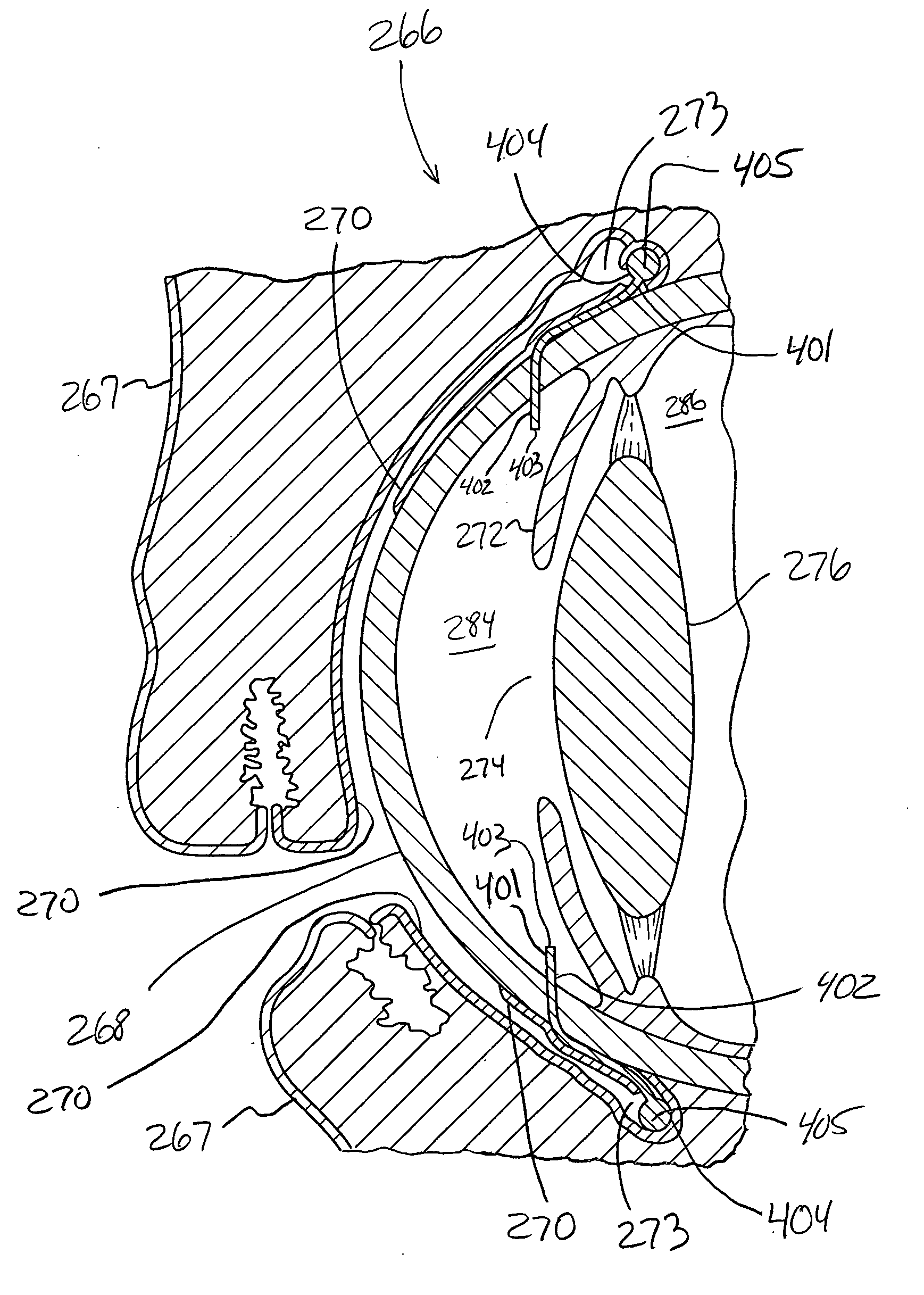
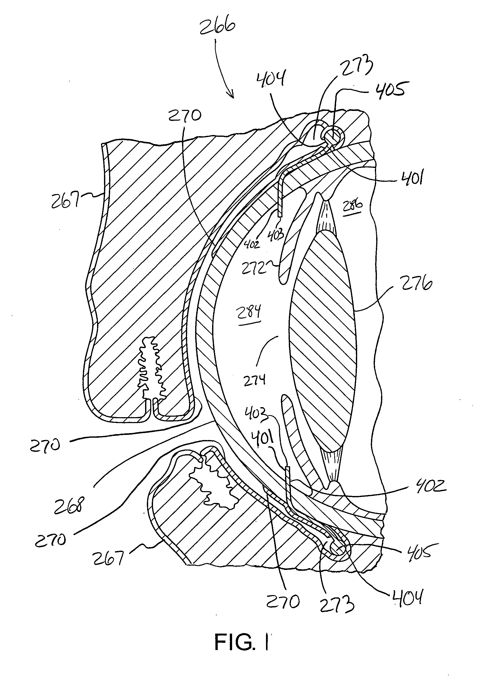
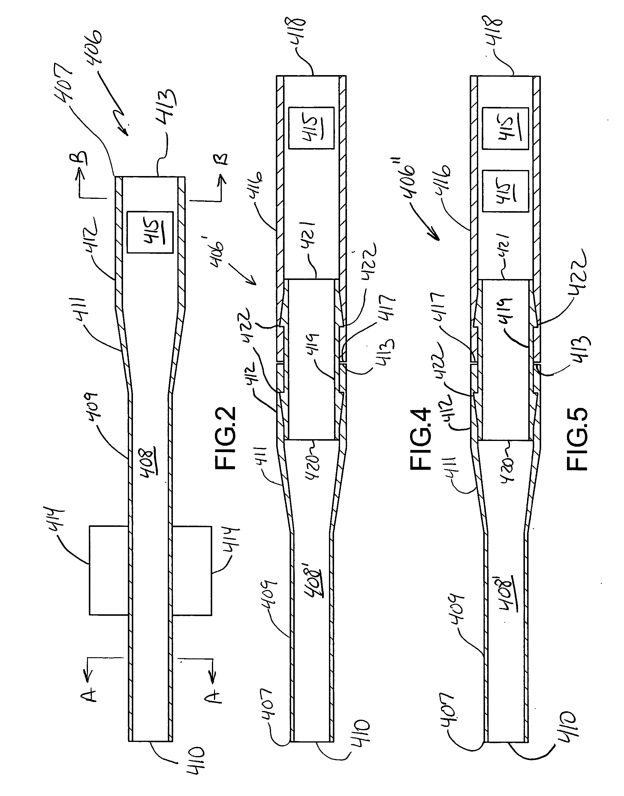
[0056] The present invention will now be described in relation to the accompanying drawings that at least assist in illustrating its various pertinent features. Generally, the present invention relates to addressing the intraocular pressure of an eye. More specifically, what may be characterized as an implant, shunt, or drainage device is directed through the eye for exposure to the anterior chamber of the eye, and extends from the anterior chamber to an appropriate drainage location or destination to accommodate a desired flow of aqueous humor out of the anterior chamber. The term “implant,” as used herein, means a device that is at least partially disposed within an appropriate biological mass. The entire implant could be disposed within a biological mass. Another option would be for part of the implant to be disposed within a biological mass, and for another part of the implant to be disposed externally of the biological mass or at least provide for fluid communication externally...


PUM


Abstract

An integral conduit (407) in the formed of stepped tubing defines at least part of a drainage flow path (408/408′) that accommodates a flow rate of at least about 0.15 microliters/minute/mm2/mm-Hg out of the anterior chamber (284) of the eye (266). One or more flow modules (415) may be disposed within this drainage flow path (408/048′) and are located exteriorly of the eye (266). Each flow module (415) may be in the form of a filter or a pressure regulator. In one embodiment, one flow module (415) in the form of a filter is used in combination with another flow module (415) in the form of a pressure regulator.

Description

CROSS-REFERENCE TO RELATED APPLICATIONS [0001] This patent application is a continuation-in-part of, and claims priority under 35 U.S.C. §120 to, U.S. patent application Ser. No. 11 / 095,995, that is entitled “MEMS FILTER MODULE WITH CONCENTRIC FILTERING WALLS,” and that was filed on Mar. 31, 2005. This patent application is also a continuation-in-part of, and claims priority under 35 U.S.C. §120 to, U.S. patent application Ser. No. 11 / 065,183, that is entitled “GLAUCOMA IMPLANT HAVING MEMS FILTER MODULE,” and that was filed on Feb. 24, 2005, which is a continuation-in-part of, and claims priority under 35 U.S.C. §120 to, U.S. patent application Ser. No. 10 / 911,424, that is entitled “MEMS FILTER MODULE,” and that was filed on Aug. 4, 2004, and which further claims priority under 35 U.S.C. §119 to U.S. Provisional Patent Application Ser. No. 60 / 547,252, that is entitled “MEMS FILTER MODULE,” and that was filed on Feb. 24, 2004. This patent application is also a continuation-in-part of...

Claims


Application Information

Patent Timeline
Patent Type & Authority Applications(United States)
IPC IPC(8): A61M5/00
CPCB82Y30/00A61F9/00781
Inventor KOONMEN, JAMES P.SMITH, NORMAN F.SNIEGOWSKI, JEFFRY J.BARNES, STEPHEN M.MCWHORTER, PAUL J.RODGERS, M. STEVEN
Owner BECTON DICKINSON & CO
Why Eureka
Try Eureka