
Spinal surgery system and method

a spine surgery and spine technology, applied in the field of spine surgery, can solve the problems of limited reliability of available techniques for anchoring implants in the spinal column, difficult to achieve precise positioning of devices anterior to the spinal cord using a posterior approach, and the limitations of the available options in a number of respects

Active Publication Date: 2006-02-16
SEASPINE
View PDF5 Cites 171 Cited by
  • Summary
  • Abstract
  • Description
  • Claims
  • Application Information

AI Technical Summary

Benefits of technology

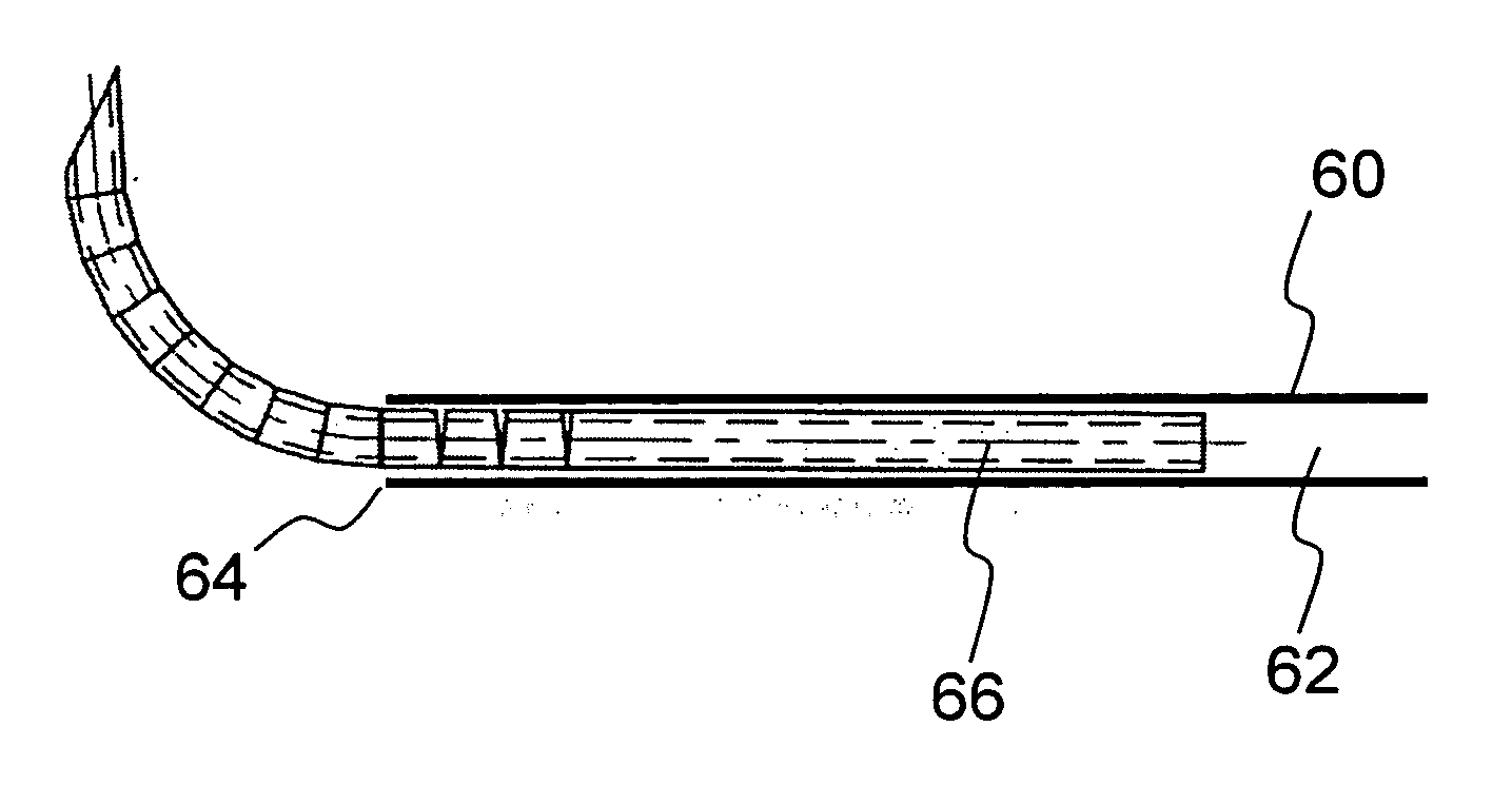
The present invention provides an apparatus and method for minimally invasive spinal surgery that allows for the formation of an arcuate tunnel through biological tissue. The apparatus includes a delivery conduit and a tunneling system. The tunneling system includes a tunneling device with a distal portion that can be deflected to a maximum deflection relative to the elements, allowing for a pre-defined arcuate state. The tunneling device is formed from a series of rigid elements interconnected at pivotal interconnection regions with parallel effective hinge axes. The invention also provides an elongated flexible guide element for deployment after removal of the tunneling system. The technical effects of the invention include improved spinal surgery techniques with reduced invasiveness and improved outcomes.

Problems solved by technology

Despite a wide range of procedures performed today as minimally invasive spinal surgery (“MISS”) procedures, there remain fundamental limitations to the available options in a number of respects.
Firstly, while a posterior approach is preferred for minimizing iatrogenic soft-tissue morbidity, it has been found difficult to achieve precise positioning of devices anterior to the spinal cord using a posterior approach.
Furthermore, the available techniques for anchoring implants in position within the spinal column are limited in their reliability and tend to generate problematic local debris.

Method used


Image

  • Spinal surgery system and method
  • Spinal surgery system and method
  • Spinal surgery system and method

Examples


Embodiment Construction

[0051] The present invention is an apparatus and method for minimally invasive spinal surgery. The invention also provides surgical techniques, advantageously implemented using the apparatus and method of the invention, for intervertebral disc repair and for vertebral body repair.

[0052] The principles and operation of a surgical apparatus and method, and surgical techniques, according to the present invention will be better understood with reference to the drawings and the accompanying description.

Surgical Apparatus and Method

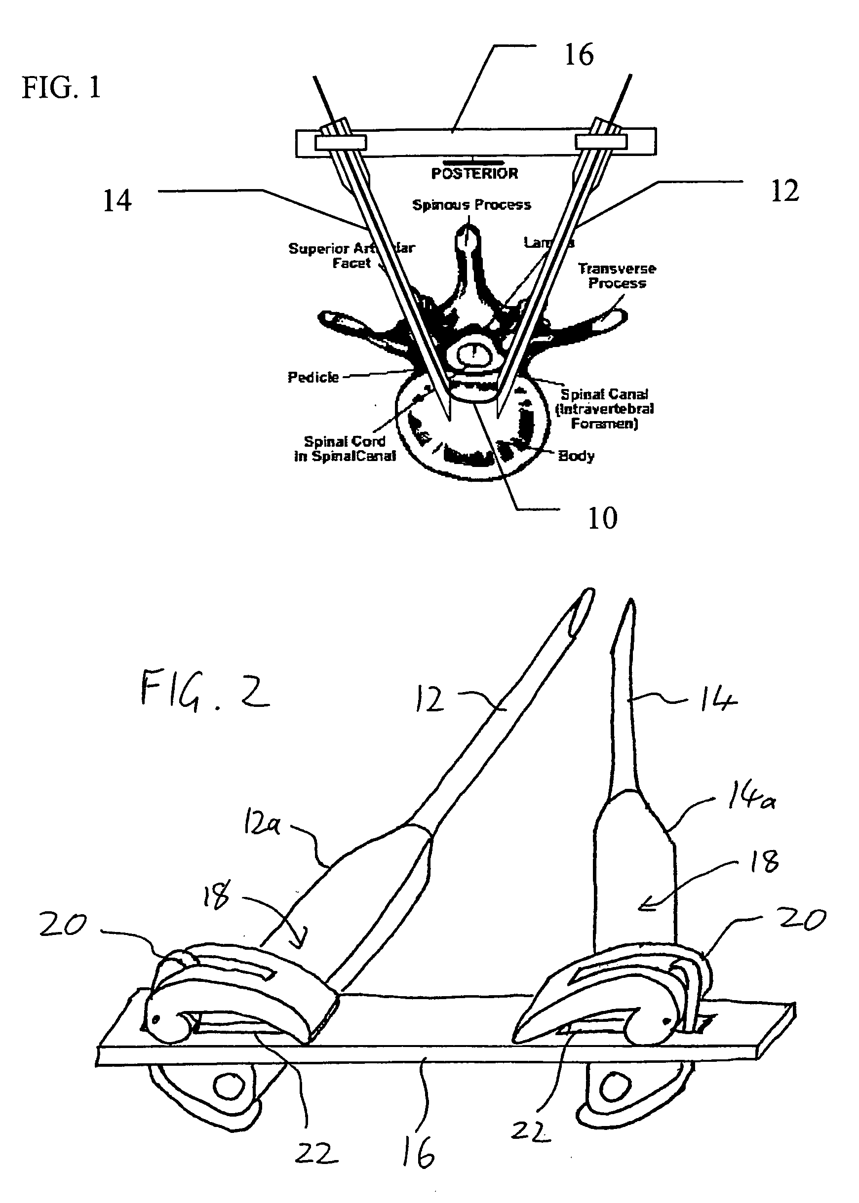
[0053] Referring now to the drawings, FIG. 1 illustrates a preferred apparatus and corresponding method for performing various minimally invasive spinal surgery (MISS) procedures according to the teachings of the present invention. In general terms, the preferred surgical method of the present invention is based on inserting an elongated flexible guide element 10 such that the guide element passes in through a first lateral posterior incision, passes throug...


PUM


Abstract

Apparatus and method for minimally invasive spinal surgery employs an elongated flexible guide element inserted so as to pass in through a first lateral posterior incision, through the spinal column anterior to the spinal cord, and out through a second lateral posterior incision contralateral to said first incision. The guide element is used to guide various elements to a desired position within the spinal column as part of the surgical procedure. Preferably, two hollow rigid tubes rigidly coupled outside the body in converging relation are used to define a working gap within the spinal column through which the guide element passes. This provides a platform for manipulation of tissues and introduction of implants anterior to the spinal cord. Procedures described include reinforcement of a degenerative intervertebral disc and restoration of a damaged vertebral body.

Description

[0001] This application is a Continuation-In-Part of Ser. No. 10 / 915,478 filed Aug. 11, 2004.FIELD AND BACKGROUND OF THE INVENTION [0002] The present invention relates to spinal surgery and, in particular, it concerns a system and method for performing various minimally invasive spinal surgical procedures. [0003] The past several years have witnessed a multitude of novel ideas and techniques for improved care for patients with spinal conditions. Some of these advances have improved the quality of life of patients suffering from degenerative disk disease with disabling low back pain. The current trend is towards less invasive approaches with less iatrogenic soft-tissue morbidity, as compared to traditional procedures with or without fusion of vertebral bones. [0004] Despite a wide range of procedures performed today as minimally invasive spinal surgery (“MISS”) procedures, there remain fundamental limitations to the available options in a number of respects. Firstly, while a posterio...

Claims


Application Information

Patent Timeline
Patent Type & Authority Applications(United States)
IPC IPC(8): A61B17/00
CPCA61B17/1642A61B17/1671A61B17/1757A61B17/7094A61F2250/0098A61F2002/30242A61F2002/4415A61F2002/444A61F2230/0071A61F2002/3008A61B2017/00309A61B2017/00314A61B2017/00323A61B2017/320056
Inventor SIEGAL, TZONY
Owner SEASPINE
Learn More