Magnetically biased eddy current sensor

a magnetic field and eddy current technology, applied in the field of magnetic sensing, can solve problems such as destroying data on the hard drive, and achieve the effect of accurate sensing of small magnetic fields

Inactive Publication Date: 2006-02-23
HONEYWELL INT INC
View PDF10 Cites 44 Cited by
  • Summary
  • Abstract
  • Description
  • Claims
  • Application Information

AI Technical Summary

Benefits of technology

[0016] It is further aspect of the embodiments to use biased GMR elements only for applications that can tolerate the magnetic bias field. Some applications, such as reading computer hard drives, require accurate sensing of small magnetic fields....

Problems solved by technology

However, using a magnet to bias a GMR eleme...

Method used


Image

  • Magnetically biased eddy current sensor
  • Magnetically biased eddy current sensor
  • Magnetically biased eddy current sensor

Examples


Embodiment Construction

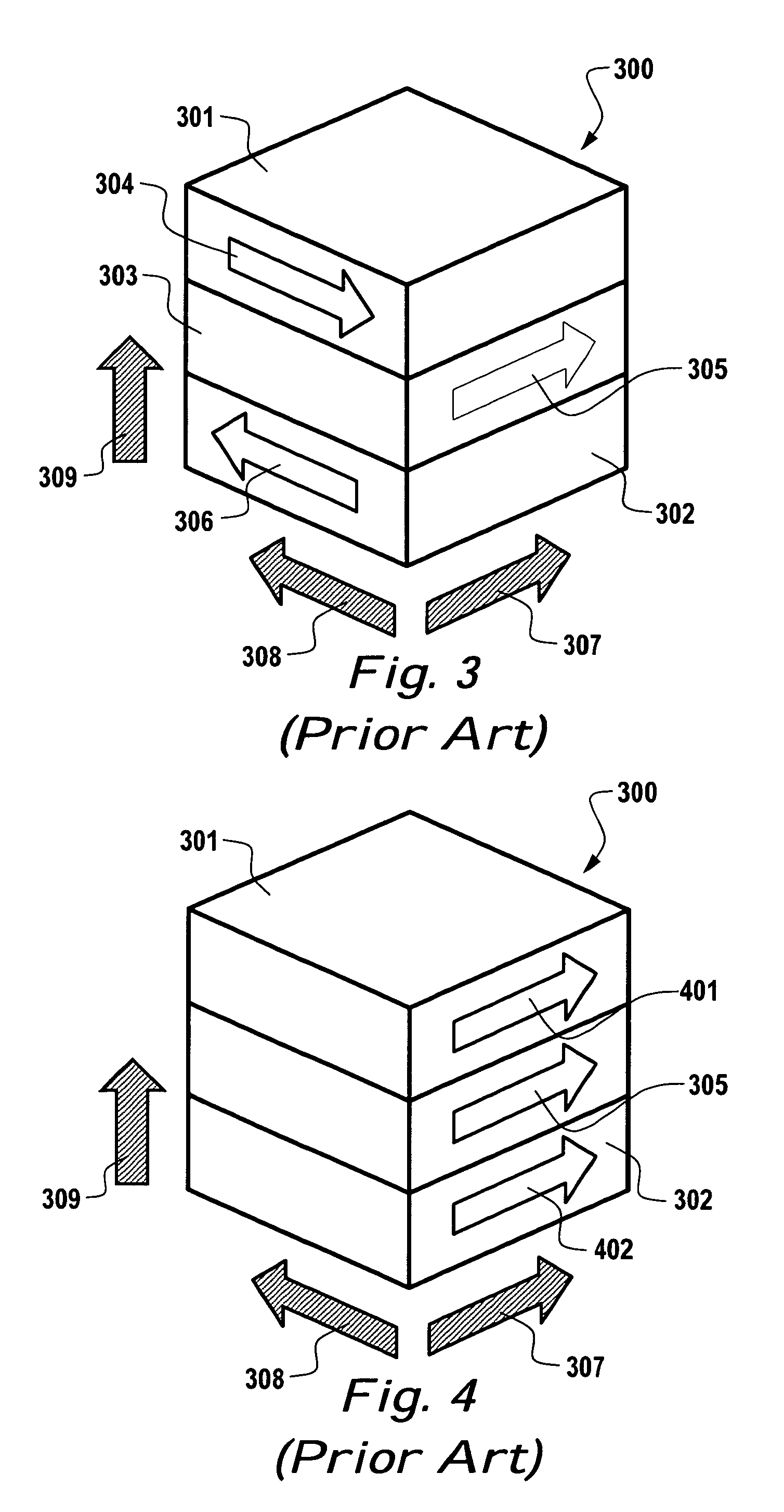
[0038] Biasing is a technique commonly used in electronic circuitry, especially in electronic amplifiers. It can be applied to GMR elements with the realization that the bias must be applied magnetically whereas electronic circuits are biased electrically. The idea is to magnetically bias the GMR element to be in a favorable region of its response curve. A GMR element's response curve is its electrical resistance when subjected to different magnetic field strengths. When in the rest state, a GMR element exhibits a small resistance change for large magnetic field strength changes.

[0039] Similarly, in the active state, a GMR element again exhibits a small resistance change for large magnetic field strength changes. A biased GMR element is not in the rest state or the active state, but somewhere in between. The biased GMR element exhibits large resistance changes for small changes in magnetic field strength. Therefore, applications that require the detection of small magnetic fields a...


PUM


Abstract

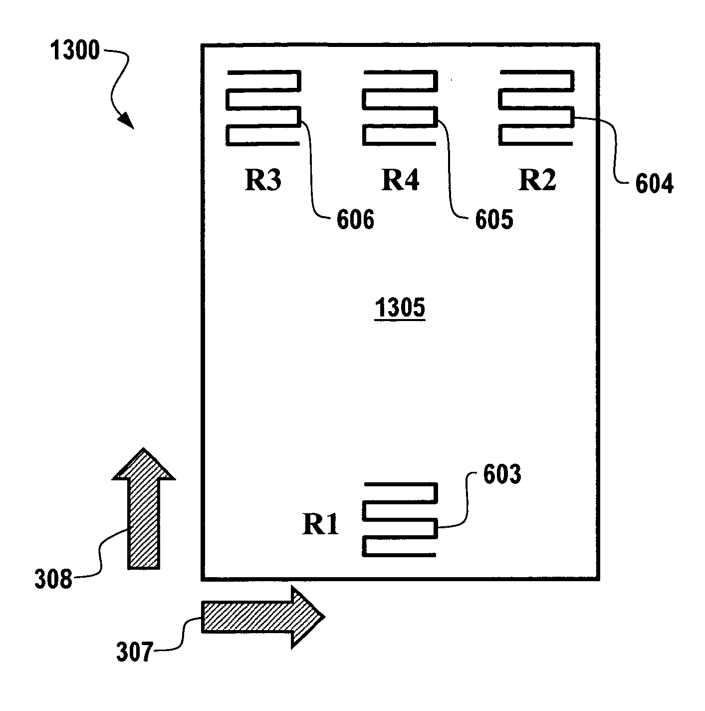
Eddy currents arise when a conductive material moves through a magnetic field. Eddy currents, like all electric currents, generate a magnetic field. The generated magnetic field can be detected and measured through use of one or more magnetically biased GMR elements. In general, an eddy current sensor can be configured, which includes a magnet, and a first giant magnetoresistive element placed such that the magnetic field from the magnet biases the giant magnetoresistive element along its primary axis.

Description

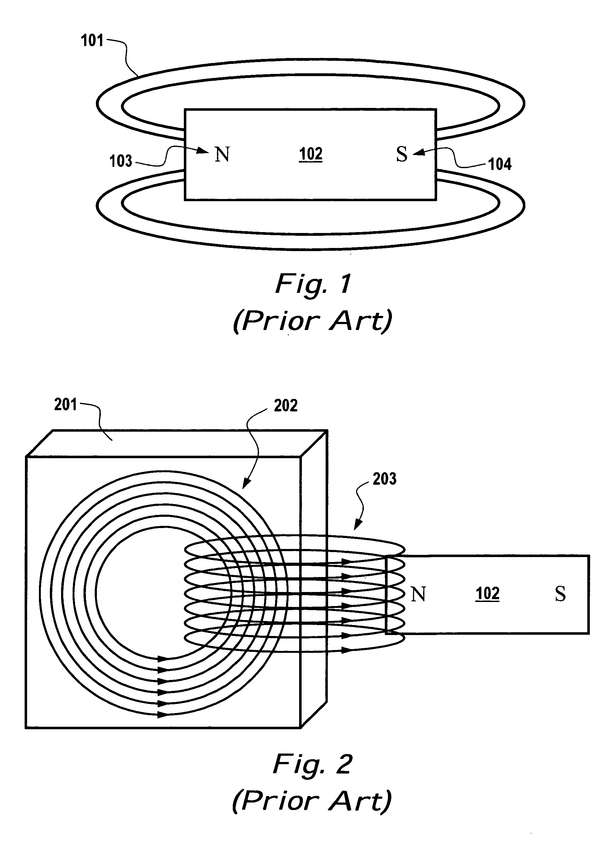
TECHNICAL FIELD [0001] Embodiments relate to the field of magnetic sensing. Embodiments also relate to the use of giant magnetoresistive sensing to detect the eddy currents in a conductor passing through a magnetic field. BACKGROUND OF THE INVENTION [0002] Many applications require the ability to sense or detect the movement of an electrically conductive material. Sensing the rotation of a turbine with aluminum fins is one example. Aluminum is an electrically conductive material and the fins move as the turbine rotates. There are many ways to measure turbine rotation, but they usually require fixing a target to the rotating part. The target adds complexity and a possible failure point to the structure. [0003] Magnets, such as the one shown in FIG. 1, labeled as prior art, are well known devices. A magnet 102 has a north pole 103, a south pole 104, and a magnetic field often indicated by magnetic field lines 101. Magnets have many interesting properties. One property is attracting pi...

Claims


Application Information

Patent Timeline
IPC IPC(8): G01N27/82
CPCB82Y25/00G01R33/093G01N27/9033G01N27/9006
Inventor LAMB, WAYNE A.JOHNSON, CURTIS B.
Owner HONEYWELL INT INC
Why Eureka
Try Eureka