Polarized light separating element embedded with thin metallic wire

Inactive Publication Date: 2006-02-23
SUMITOMO CHEM CO LTD
View PDF2 Cites 20 Cited by
  • Summary
  • Abstract
  • Description
  • Claims
  • Application Information

AI Technical Summary

Benefits of technology

[0009] A polarized light separating element according to the present invention has stable structure of a m

Problems solved by technology

While a conventional metal wire grid is formed on a substrate surface, a structure of the metal wire grid is easily broken and inferior in durability.
Also,

Method used


Image

  • Polarized light separating element embedded with thin metallic wire
  • Polarized light separating element embedded with thin metallic wire
  • Polarized light separating element embedded with thin metallic wire

Examples


example 1

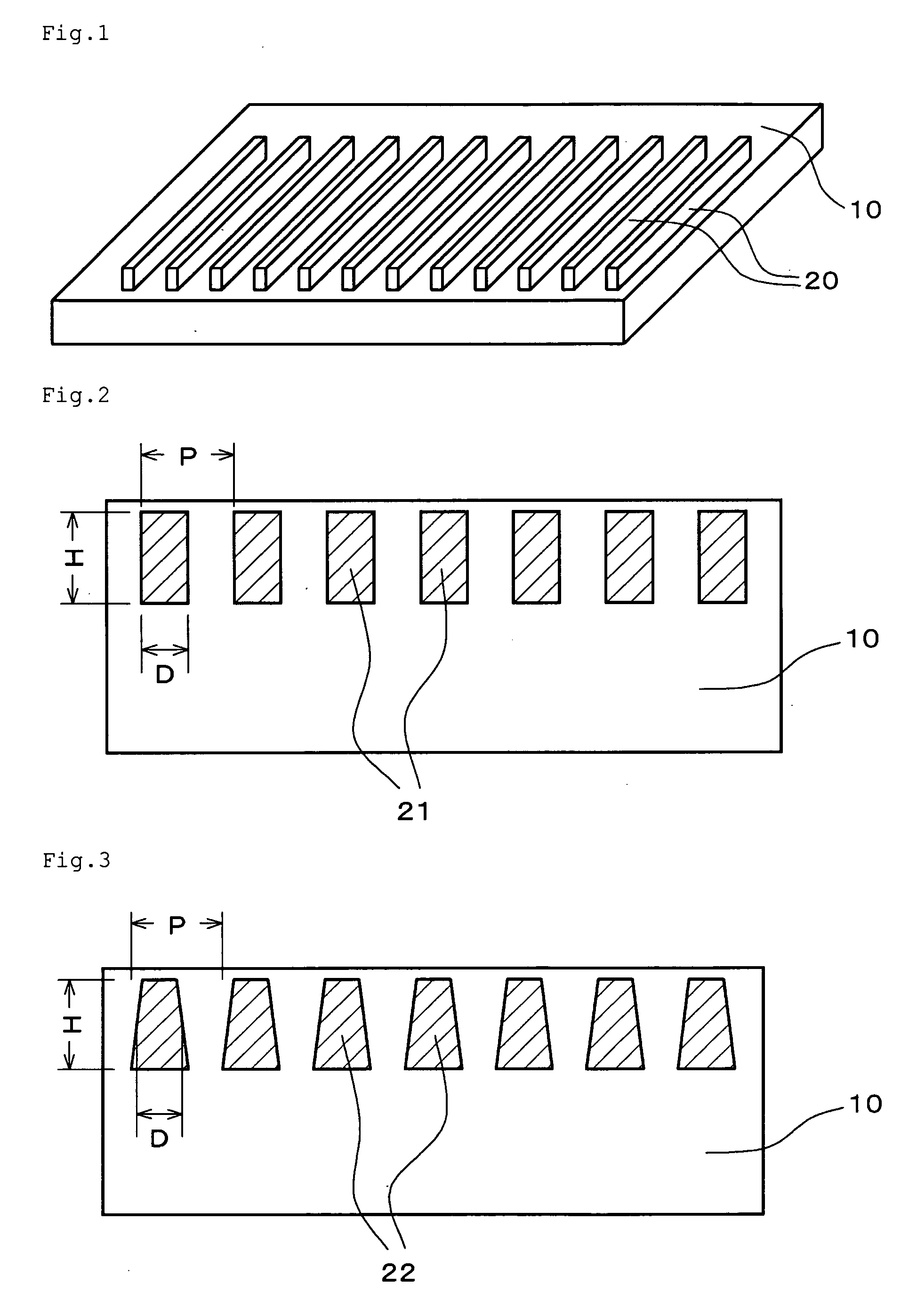
[0067] Thin metallic wires are made of aluminum, and the cross-sectional shape thereof is approximately a rectangle having a width of 78 nm and a height of 150 nm. The whole surface of these thin wires is covered with an aluminum oxide film having a thickness of 20 nm. These thin wires are embedded at a pitch of 150 nm in one surface of a polymeric film having a refractive index of approximately 1.5 in a state such that a height direction of a cross section of the thin wires is a thickness direction of the film and the thin wires are arrayed in a row so as to be parallel to each other. The ratio (D / P) of the width to the pitch of the thin wires is 78 / 150=0.52. This polarized light separating element has approximately a cross-sectional shape shown in FIG. 2. The polarized light separative power of this polarized light separating element is approximately 89%.

example 2

[0068] Thin metallic wires are made of aluminum, and the cross-sectional shape thereof is a trapezoid (wedge) having a long side of 50 nm, a short side of 30 nm and a height of 150 nm. These thin wires are embedded at a pitch of 150 nm in one surface of a polymeric film having a refractive index of approximately 1.5 in a state such that a height direction of a trapezoid in a cross section of the thin wires is a thickness direction of the film and the thin wires are arrayed in a row so as to be parallel to each other. The ratio (D / P) of the width to the pitch of the thin wires in the central portion in a height direction of a trapezoid is 40 / 150=0.26. This polarized light separating element has approximately a cross-sectional shape shown in FIG. 3. The polarized light separative power of this polarized light separating element is approximately 89%.

example 3

[0069] Thin metallic wires are made of aluminum, and the cross-sectional shape thereof is an isosceles triangle having a base of 80 nm and a height of 150 nm. These thin wires are embedded at a pitch of 150 nm in one surface of a polymeric film having a refractive index of approximately 1.5 in a state such that a height direction of an isosceles triangle in a cross section of the thin wires is a thickness direction of the film and the thin wires are arrayed in a row so as to be parallel to each other. The ratio (D / P) of the width to the pitch of the thin wires in the central portion in a height direction of a triangle is 40 / 150=0.26. This polarized light separating element has approximately a cross-sectional shape shown in FIG. 4. The polarized light separative power of this polarized light separating element is approximately 89%.


PUM


Abstract

An object of the present invention is to provide a high-performance polarized light separating element having stable structure and superior durability, whose product with a large area can easily be manufactured. There is provided a polarized light separating element comprising a plurality of thin metallic wires 21, 21 embedded and arrayed in a planar substrate 10 so as to be parallel to each other, wherein the pitch (P) of the wires 21, 21 is 100 to 300 nm, the ratio (D/P) of the width (D) of the wires 21, 21 to the pitch (P) of the wires is 0.1 to 0.6, and the height (H) of the wires 21, 21 in a cross section orthogonal to a lengthwise direction of the wires is 50 to 500 nm. With regard to the wires 21, 21, a surface thereof may be covered with a metallic oxide film. The substrate 10 is preferably a polymeric resin film.

Description

BACKGROUND OF THE INVENTION [0001] 1. Field of the Invention [0002] The present invention relates to a polarized light separating element used for a liquid crystal display device, a projection display device and a headlamp of an automobile. [0003] 2. Description of the Related Art [0004] A polarized light separating element selectively transmits only linearly polarized light vibrating in a specific direction and reflects linearly polarized light vibrating in a direction orthogonal to the specific direction. The following have been known as such a polarized light separating element; an element made of a multilayer laminate of several kinds of polymeric films having different refractive anisotropy, and an element made of a metal wire grid. A polarized light separating element of a metal wire grid type is described, for example, in WO 00 / 079317 Publication (=Japanese Patent National Publication No. 2003-502758) and JP No. 10-73722 A. These polarized light separating elements of a metal...

Claims


Application Information

Patent Timeline
IPC IPC(8): G02B5/30
CPCG02B5/3058G02B5/30G02F1/1335
Inventor HAYASHI, NARUTOSHIFUJII, TAKASHI
Owner SUMITOMO CHEM CO LTD
Why Eureka
Try Eureka