Disc drive suspension

a technology of disc drive and suspension, which is applied in the direction of magnetic recording, data recording, instruments, etc., can solve the problems of lowering the appearance quality of the suspension or damaging the welding jig, and achieve the effect of reducing the weight without lowering the welding strength

Active Publication Date: 2006-02-23
NHK SPRING CO LTD
View PDF6 Cites 7 Cited by
  • Summary
  • Abstract
  • Description
  • Claims
  • Application Information

AI Technical Summary

Benefits of technology

[0009] Accordingly, the object of this invention is to provide a disc drive s...

Problems solved by technology

If the thin partially etched portion is subjected to laser spot welding, a laser beam sometimes may p...

Method used


Image

  • Disc drive suspension
  • Disc drive suspension
  • Disc drive suspension

Examples


first embodiment

[0022] this invention will now be described with reference to FIGS. 1 to 5.

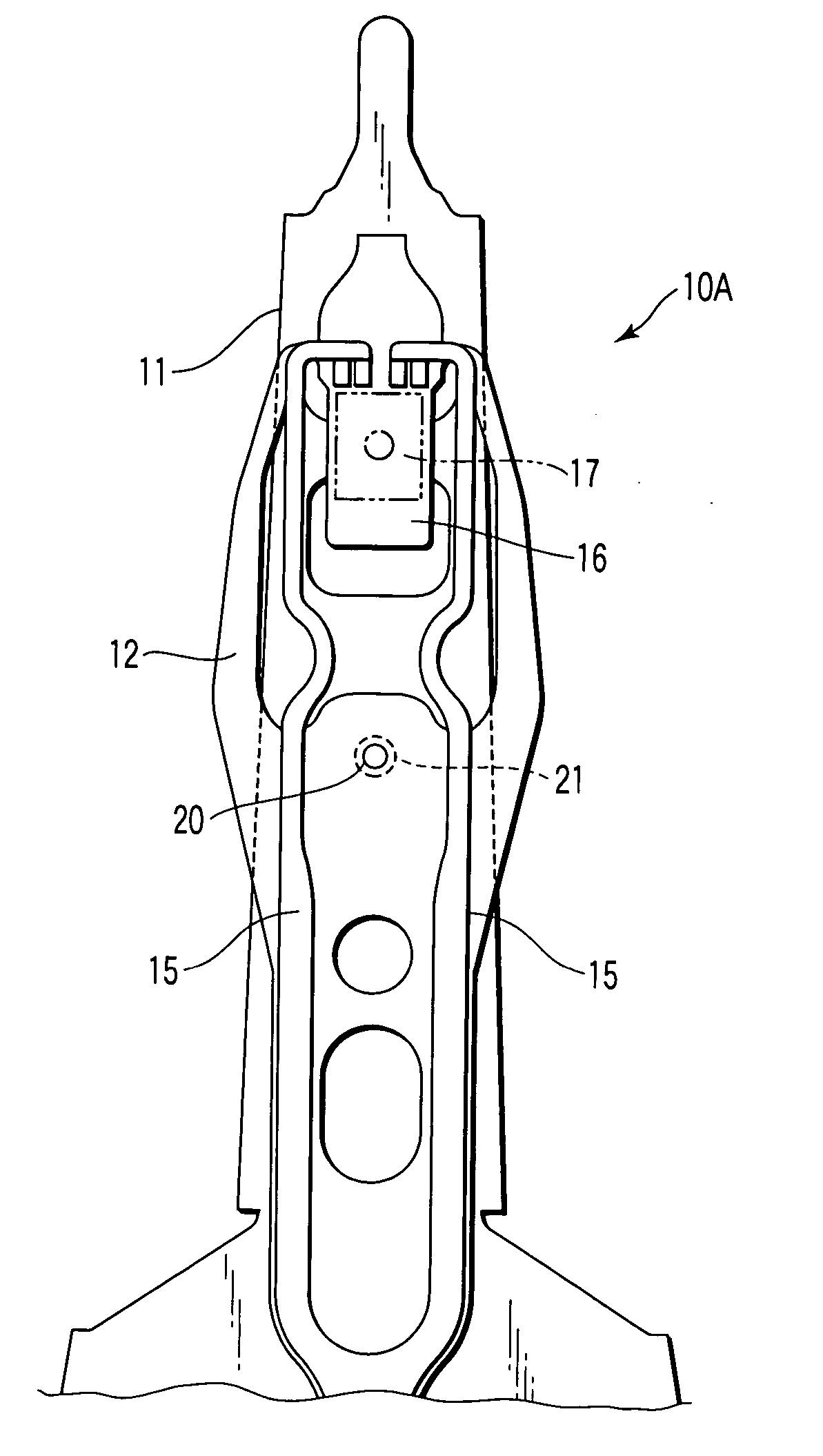
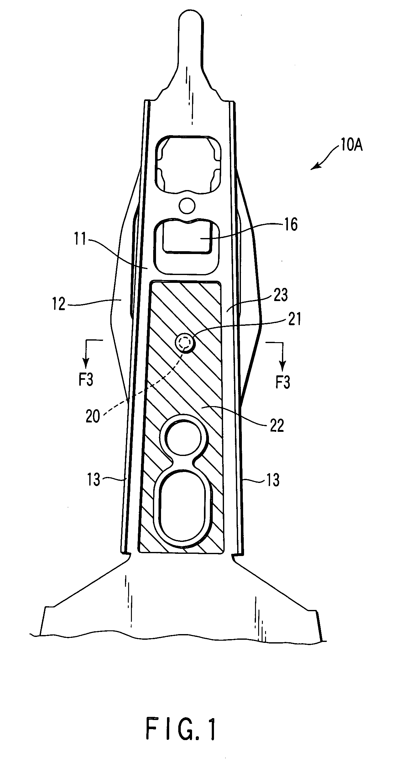
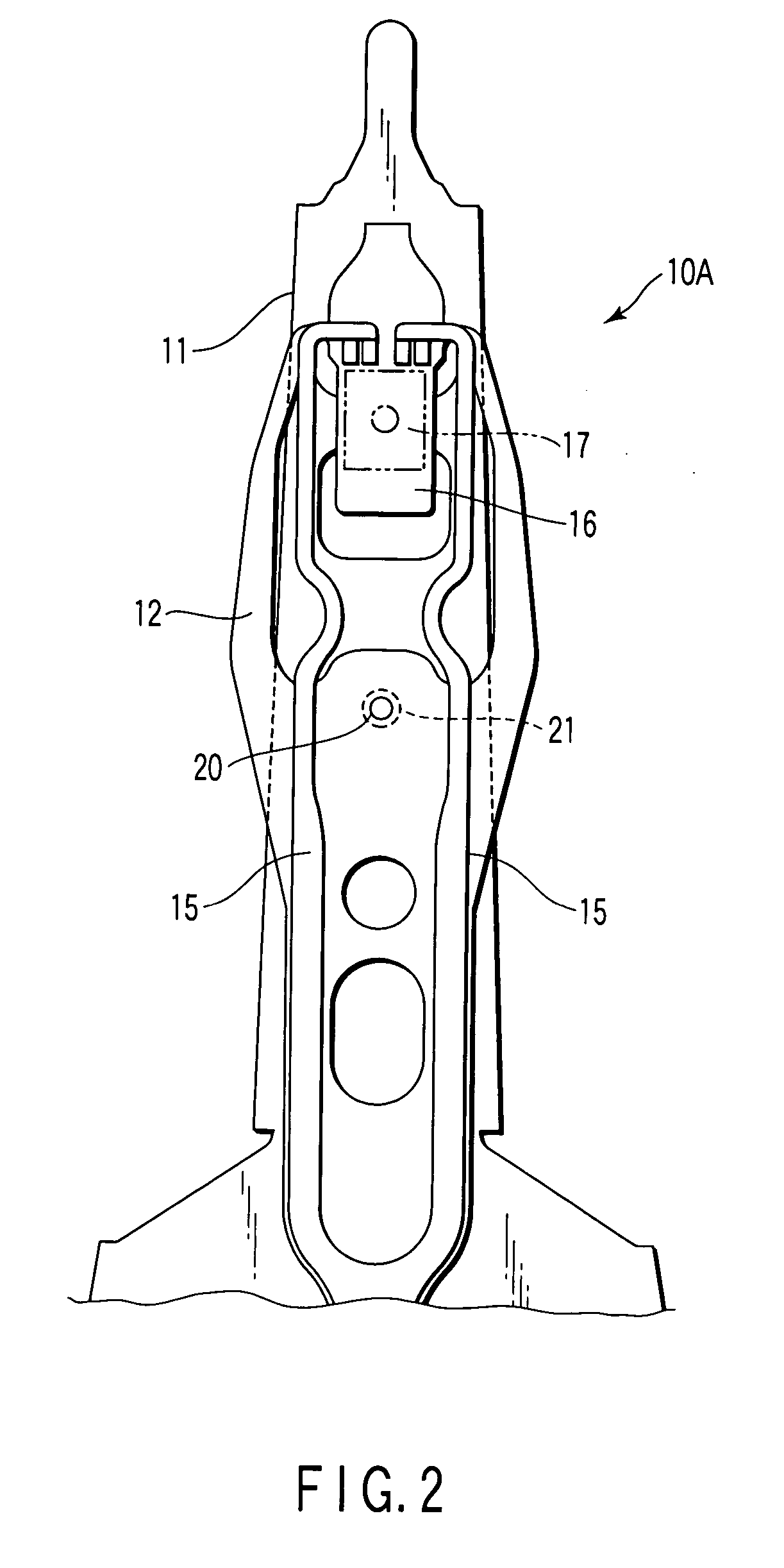
[0023]FIGS. 1 and 2 show an example of a disc drive suspension 10A. The suspension 10A comprises a load beam 11 and a flexure 12 lapped on the load beam 11.

[0024] The load beam 11 is formed of a stainless-steel plate with a thickness of about 50 to 100 μm (e.g., 50 μm). As shown in FIG. 3, bent portions 13 are formed individually on the opposite side edges of the load beam 11.

[0025] The flexure 12 is formed of a metal plate thinner than the load beam 11, e.g., a stainless-steel plate with a thickness of about 10 to 20 μm. Any other metal than stainless steel may be used as a material for the load beam 11.

[0026] As shown in FIG. 2, the flexure 12 is provided with a wiring portion 15. The wiring portion 15 is composed of a write conductor and a read conductor extending along the flexure 12, an electrical insulating layer (not shown) formed between the flexure 12 and the conductors, and an electrical insulati...


PUM


Abstract

In a disc drive suspension having a load beam and a flexure lapped on the load beam, the load beam and the flexure are fixed to each other by a laser weld. The load beam has an insular region including the laser weld of the load beam and a partially etched portion formed around the insular region. The partially etched portion is thinner than the insular region. The etched portion is formed around the whole circumference of the insular region.

Description

CROSS-REFERENCE TO RELATED APPLICATIONS [0001] This application is based upon and claims the benefit of priority from prior Japanese Patent Application No. 2004-241233, filed Aug. 20, 2004, the entire contents of which are incorporated herein by reference. BACKGROUND OF THE INVENTION [0002] 1. Field of the Invention [0003] This invention relates to a disc drive suspension used in an information processor, such as a personal computer. [0004] 2. Description of the Related Art [0005] A hard disc drive (HDD) used in an information processor, such as a personal computer, comprises a carriage that can turn around an axis. The carriage is turned around the axis by a positioning motor. The carriage comprises an actuator arm, a suspension (disc drive suspension) provided on the distal end portion of the arm, a head portion including a slider mounted on the suspension, and the like. When the disc rotates, the slider slightly floats above a surface of the disc, and an air bearing is formed bet...

Claims


Application Information

Patent Timeline
IPC IPC(8): G11B5/48
CPCG11B5/4833G11B5/4826
Inventor KASHIMA, HIDEKI
Owner NHK SPRING CO LTD
Why Eureka
Try Eureka