Gun drill

a gun drill and assembly technology, applied in the field of gun drills, can solve the problems of loss of rotational alignment, difficulty in removing the tip, disturbance of fluid and chips flow,

Active Publication Date: 2006-02-23
ISCAR LTD
View PDF15 Cites 14 Cited by
  • Summary
  • Abstract
  • Description
  • Claims
  • Application Information

AI Technical Summary

Benefits of technology

[0022] If desired, an axially rearwardly facing cutting-head intermediate surface is located between the cutting-head fixation surface and the cutting-head peripheral surface, and an axially forwardly facing shank intermediate surface is located between the shank fixation surface and the shank peripheral surface. When the cutting-head is secured in the shank, a second gap exists between the cutting-head and shank intermediate surfaces.
[0023] Alternatively, in the secured position, a rear gap exists between a generally axially rearwardly facing cutting-head rear surface disposed adjacent the cutting-head cylindrical surface and a generally axially forwardly facing shank rear surface disposed adjacent the

Problems solved by technology

However, even if these surfaces are initially precisely fitted, deformation during work may cause dimensional variations, and because there is no definite rotational stop to prohibit over rotation, the parts can rotate relative to each other, especially under working loads, thereby losing their rotational alignment, leading to over-tightening, difficulty in removing the tip, and disturbance to the flow of fluid and chips.
Additionally, since the cutting-head is inserted into the driving section, a clearance fit has to exist between the cylindrical surface of the cutting-head and the hollow sleeve of the driving section, thereby preventing precise axial alignment between the two parts.
However, lack of positive stopping and torque-transmitting means can cause the problems mentioned above, i.e., loss of rotational alignment, over-tightening, difficulty in removing the tip, and disturbanc

Method used


Image

  • Gun drill
  • Gun drill
  • Gun drill

Examples


first embodiment

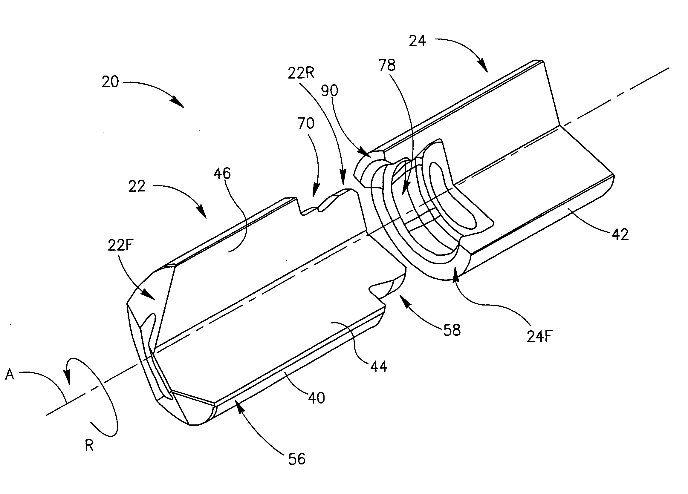
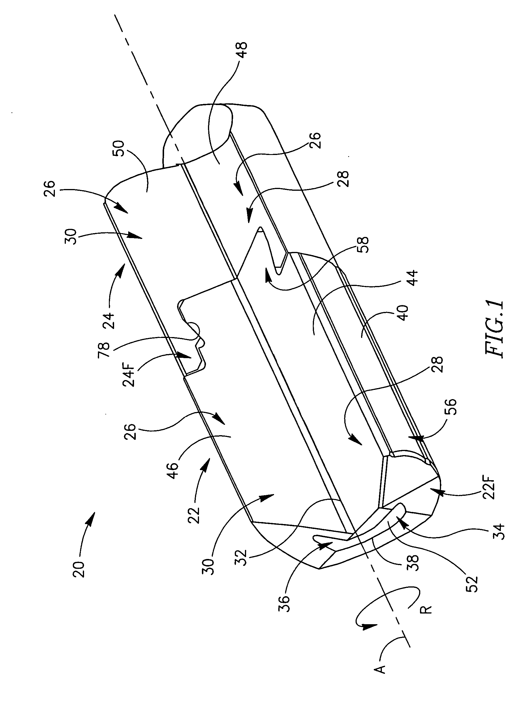
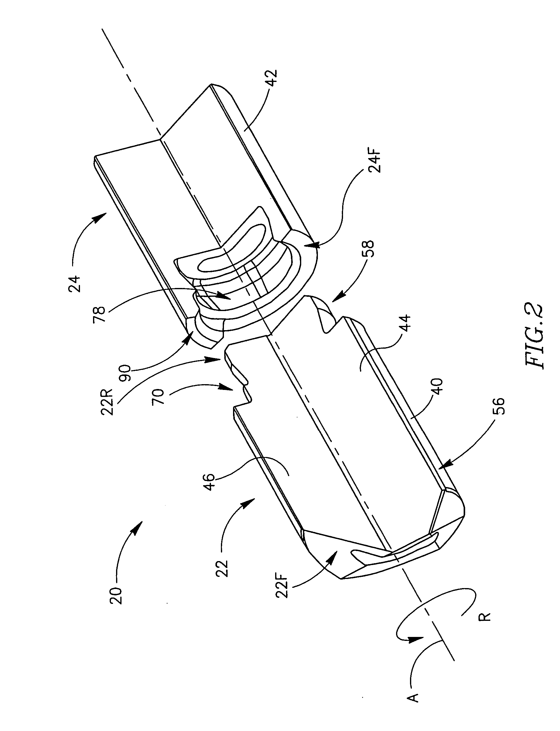
[0048] A gun-drill 20 in accordance with the present invention is shown in FIG. 1. The gun-drill 20 has a direction of rotation R around a longitudinal axis of rotation A defining a front-to-back direction, and comprises a cutting-head 22 detachably secured to a shank 24 at a shank forward end 24F. A single, straight flute 26 extends axially along the shank 24 and the cutting-head 22, and comprises leading and trailing faces 28, 30, disposed at a flute angle γ to each other. The flute leading and trailing faces 28, 30 meet at a flute apex 32 adjacent the axis of rotation A. The gun-drill 20 further comprises a fluid conduit 34 extending axially therethrough, comprising a conduit inner wall 36 and a fluid discharge outlet 38 at a cutting-head forward end 22F. When the cutting-head 22 is mounted in an operational, secured position in the shank 24, cutting-head and shank peripheral surfaces 40, 42, cutting-head and shank leading and trailing faces 44, 48, 46, 50, and cutting-head and s...

second embodiment

[0058] The gun-drill 220 in accordance with the second embodiment has an axis of rotation A and a direction of rotation R defined much in the same manner as the axis of rotation A and a direction of rotation R of the gun-drill 20 in accordance with one embodiment. The gun-drill 220 has a cutting-head 222 detachably secured to a shank 224 at a shank forward end 224F. Both the shank 224 and the cutting-head 222 have a single, straight flute 226 extending axially along the shank 224 and the cutting-head 222. The flute has leading and trailing faces 228, 230 meeting at a flute apex 232 adjacent the axis of rotation A. A fluid conduit 234 having a conduit inner wall 236 and a fluid discharge outlet 238 formed at a cutting-head forward end 222F extends axially through the gun-drill 220. When the cutting-head 222 is mounted in an operational, secured position in the shank 224, cutting-head and shank peripheral surfaces 240, 242, cutting-head and shank leading and trailing faces 244, 248, 2...


PUM

PropertyMeasurementUnit
Angleaaaaaaaaaa
Angleaaaaaaaaaa
Angleaaaaaaaaaa

Abstract

A gun-drill comprises a cutting-head detachably secured to a shank, having a common longitudinal axis and comprising mating peripheral surfaces. A shank coupling portion comprises a forwardly tapering shank fixation surface is formed at a front end of the shank, and a cutting-head coupling portion comprising a forwardly tapering cutting-head fixation surface is formed at a rear end of the cutting-head. Both the shank and the cutting-head coupling portion extend over a peripheral coupling angle φ of more than 180°. The shank and the cutting-head are assembled by positioning the cutting-head leading face in front of the shank trailing face, slidably inserting the cutting-head coupling portion into the shank coupling portion laterally to the axis of rotation A and rotating the cutting-head relative to the shank in a direction opposed to the direction of rotation R so that the cutting-head coupling portion and the shank coupling portion interlock co-axially.

Description

FIELD OF THE INVENTION [0001] The present invention relates to a gun-drill assembly having a detachably secured cutting-head, and a single, straight flute. BACKGROUND OF THE INVENTION [0002] U.S. Pat. No. 3,304,816 discloses a multi-section drill, separable from its driving means, which uses a coupling mechanism of a mating undercut arrangement in the form of a helix on corresponding male and female ends of the sections to coaxially join the sections together, detachably securing a cutting-head (driven section) in a shank (driving section) of the drill. The driving section (shank) comprises a hollow cylindrical sleeve on a driving end thereof; an undercut in the sleeve in coaxial relationship therewith; two non-parallel edge surfaces on the undercut, one edge having a helix thereon, while the other surface is flat throughout its full length and perpendicular to the rotational axis of the tool; and a back taper on the helix. The driven section (cutting-head) comprises a generally cyl...

Claims


Application Information

Patent Timeline
IPC IPC(8): B23B51/00B23BB23B51/04
CPCB23B51/0486B23B2251/02B23B2251/424Y10T408/9095Y10T408/03Y10S408/713Y10T408/455Y10T408/892Y10T408/9098Y10T408/90993Y10S408/705Y10T408/907B23B51/066B23B51/04B23B51/00B23B51/06
Inventor HECHT
Owner ISCAR LTD
Why Eureka
Try Eureka