Flat panel display device including a conductive compressible body

a display device and compressible body technology, applied in the direction of coupling device connection, instruments, printed circuits, etc., can solve the problems of not working the small clip of a small-screen lcd module manufactured by the cog module is too small to work reliably with conductive tape, and the fabricating process of using conductive tape is not without problems. , to achieve the effect of reducing noise and emi

Inactive Publication Date: 2006-02-23
SAMSUNG DISPLAY CO LTD
View PDF9 Cites 48 Cited by
  • Summary
  • Abstract
  • Description
  • Claims
  • Application Information

AI Technical Summary

Benefits of technology

[0019] According to the flat panel display device, a conductive compressible body for electrically connecting the

Problems solved by technology

Although this configuration achieves the desired electrical connections, electrically connecting the chip to the ground pattern through the screw complicates the fabricating process of the LCD device.
While this conductive tape configuration works for larger LCD modules, the clip for a small-screen LCD module manufactured by the COG mo

Method used


Image

  • Flat panel display device including a conductive compressible body
  • Flat panel display device including a conductive compressible body
  • Flat panel display device including a conductive compressible body

Examples


embodiment 1

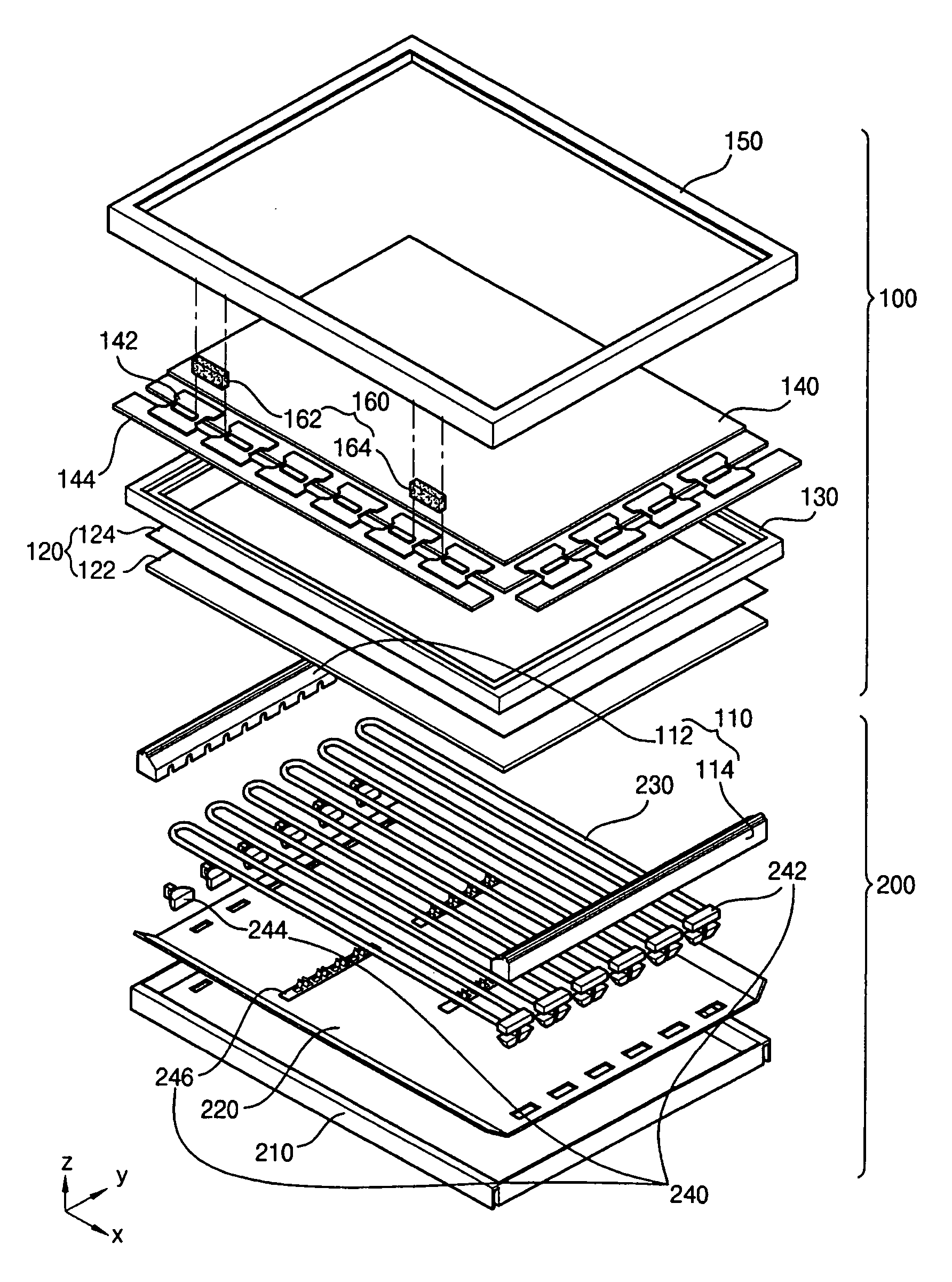
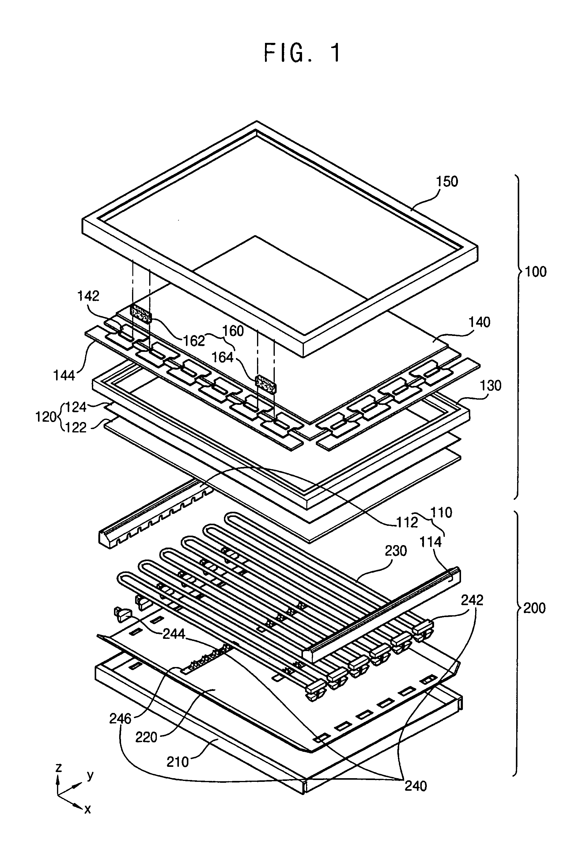
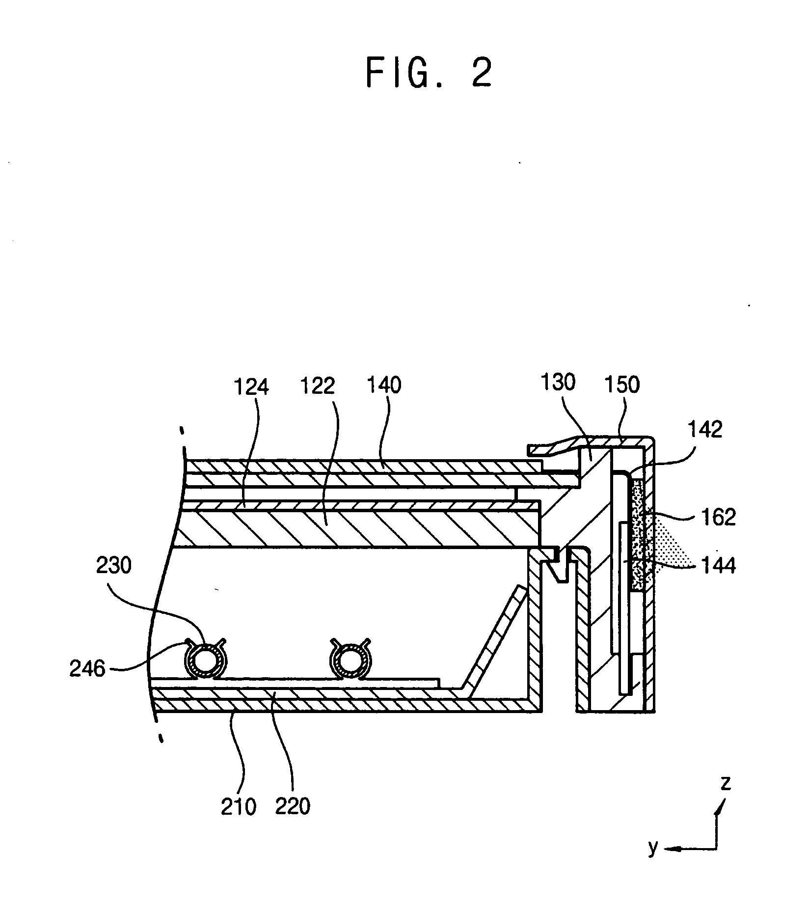
[0039]FIG. 1 is an exploded perspective view showing a flat panel display device according to a first embodiment of the present invention. FIG. 2 is an enlarged cross-sectional view showing the flat panel display device of FIG. 1. FIG. 3 is a partially cut out enlarged perspective view showing the flat panel display device of FIG. 1.

[0040] Referring to FIGS. 1 to 3, the flat panel display device includes a display panel assembly 100 in an upper portion of the flat panel display device and a backlight assembly 200 in a lower portion of the flat panel display device.

[0041] The display panel assembly 100 includes a side mold unit 110, a brightness enhancing unit 120, an upper mold 130, a flat panel 140, a top chassis 150 and a conductive compressible body 160, and receives the light emitted from the backlight assembly 200 to display an image.

[0042] The side mold unit 110 includes a first side mold 112 and a second side mold 114. The side mold unit 110 guides the backlight assembly 2...

embodiment 2

[0063]FIG. 7 is an exploded perspective view showing a flat panel display device according to a second embodiment of the present invention. The flat panel display device is of the chip on glass (COG) type.

[0064] Referring to FIG. 7, the flat panel display device includes a display panel assembly 300 and a backlight assembly 200 under the display panel assembly 300. In FIG. 7, the same reference numerals will be used to refer to the same or like parts as those described in FIG. 1 and any further explanation concerning the above elements will be omitted.

[0065] The display panel assembly 300 includes a side mold unit 310, a brightness enhancing unit 320, an upper mold unit 330, a flat panel 340, a top chassis 350 and a conductive compressible body 360, and receives the light generated from the backlight assembly 200 to display an image.

[0066] The side mold unit 310 includes a first side mold 312 and a second side mold 314. The side mold unit 310 guides the backlight assembly 200, an...


PUM


Abstract

The flat panel display includes a receiving unit, a substrate and a conductive compressible body. The receiving unit receives a flat panel. The substrate has a driving circuit that applies a signal to the flat panel to display an image. The conductive compressible body electrically connects a ground pattern of the substrate to the receiving unit. Therefore, a conductive compressible body for electrically connecting is between the ground pattern of the driving circuit unit and the top chassis, so that noise and EMI are shielded.

Description

CROSS-REFERENCE TO RELATED APPLICATION [0001] This application relies for priority upon Korean Patent Application No. 2004-65329 filed on Aug. 19, 2004, the content of which is herein incorporated by reference in its entirety. BACKGROUND OF THE INVENTION [0002] 1. Field of the Invention [0003] The present invention relates to a flat panel display device, and more particularly to a flat panel display device capable of decreasing noise and electromagnetic interference (EMI). [0004] 2. Description of the Related Art [0005] Generally, a packaging method of a thin film transistor-liquid crystal display (TFT-LCD) module is classified into a tape automated bonding (TAB) packaging method and a chip on glass (COG) packaging method. Of the two methods, the latter packaging method has been developed to package a large-screen LCD panel. More particularly, the COG packaging method has been developed with the goal of decreasing the package size and a manufacturing cost. [0006] In the TAB packagin...

Claims


Application Information

Patent Timeline
IPC IPC(8): H01R12/00
CPCG02F1/133308G02F2001/133334H01R13/6599G09G2330/06H01R13/2414G09G3/36G02F1/133334G02F1/1333
Inventor MOH, SANG-MOON
Owner SAMSUNG DISPLAY CO LTD
Why Eureka
Try Eureka