Electrical connector having structures for preventing deflected-insertion

a technology of electric connectors and structures, applied in the direction of coupling device connections, coupling protective earth/shielding arrangements, instruments, etc., can solve the problems of signal shut off, poor orientation ability, follow the miniaturization trend of products, etc., to prevent deflected insertion, convenient manufacture of connectors, and small size

Inactive Publication Date: 2006-02-23
HON HAI PRECISION IND CO LTD
View PDF9 Cites 50 Cited by
  • Summary
  • Abstract
  • Description
  • Claims
  • Application Information

AI Technical Summary

Benefits of technology

[0007] It is an object of the present invention to provide an electrical connector having structures for preventing deflected insertion of a complementary connector, and with smaller size and more convenient manufacture of the connector.

Problems solved by technology

However, a bare periphery of those contacts makes them vulnerable, then have poor orientation ability.
Therefore, when a complementary connector is inserted into the power connector, nevertheless the insertion direction has just a little deflection, those non-protective contacts would be forced and tend to warp even breaking off, which may result in signals shut off.
However, this structure complexes the manufacture of the housing, and does not follow the miniaturization trend of products.

Method used


Image

  • Electrical connector having structures for preventing deflected-insertion
  • Electrical connector having structures for preventing deflected-insertion
  • Electrical connector having structures for preventing deflected-insertion

Examples


Embodiment Construction

[0015] Reference will now be made to the drawing figures to describe the present invention in detail.

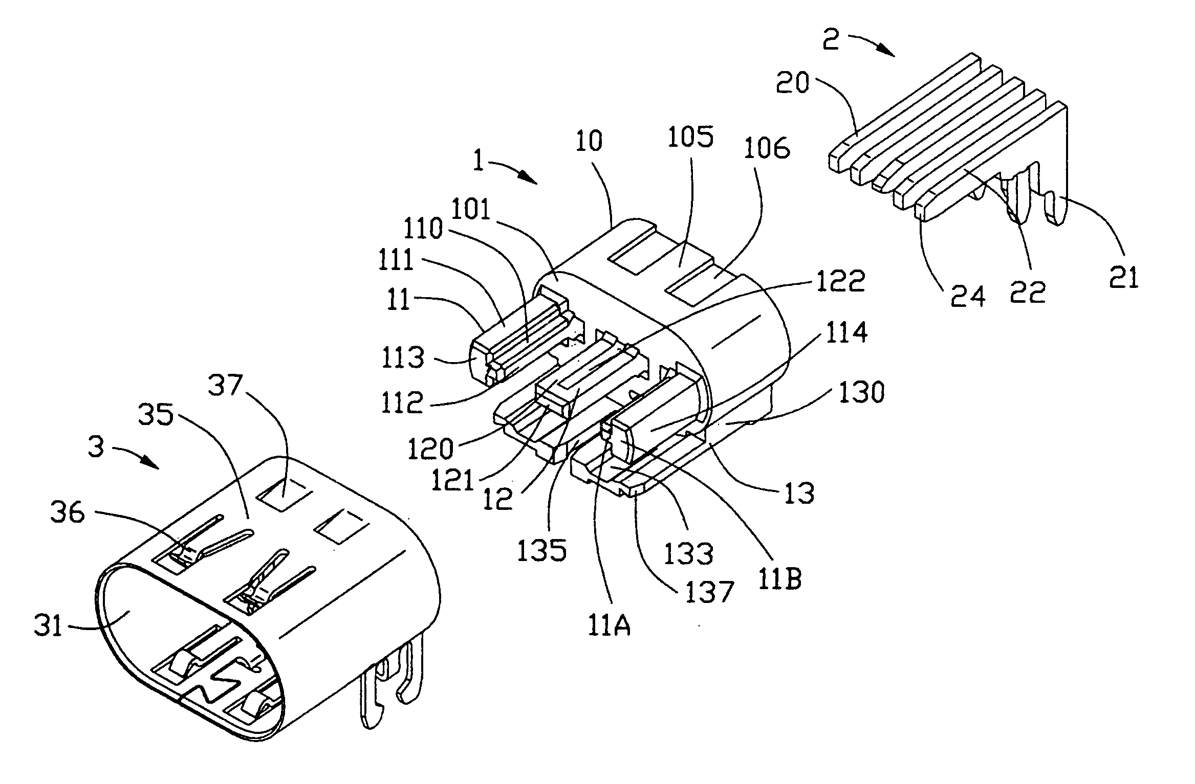
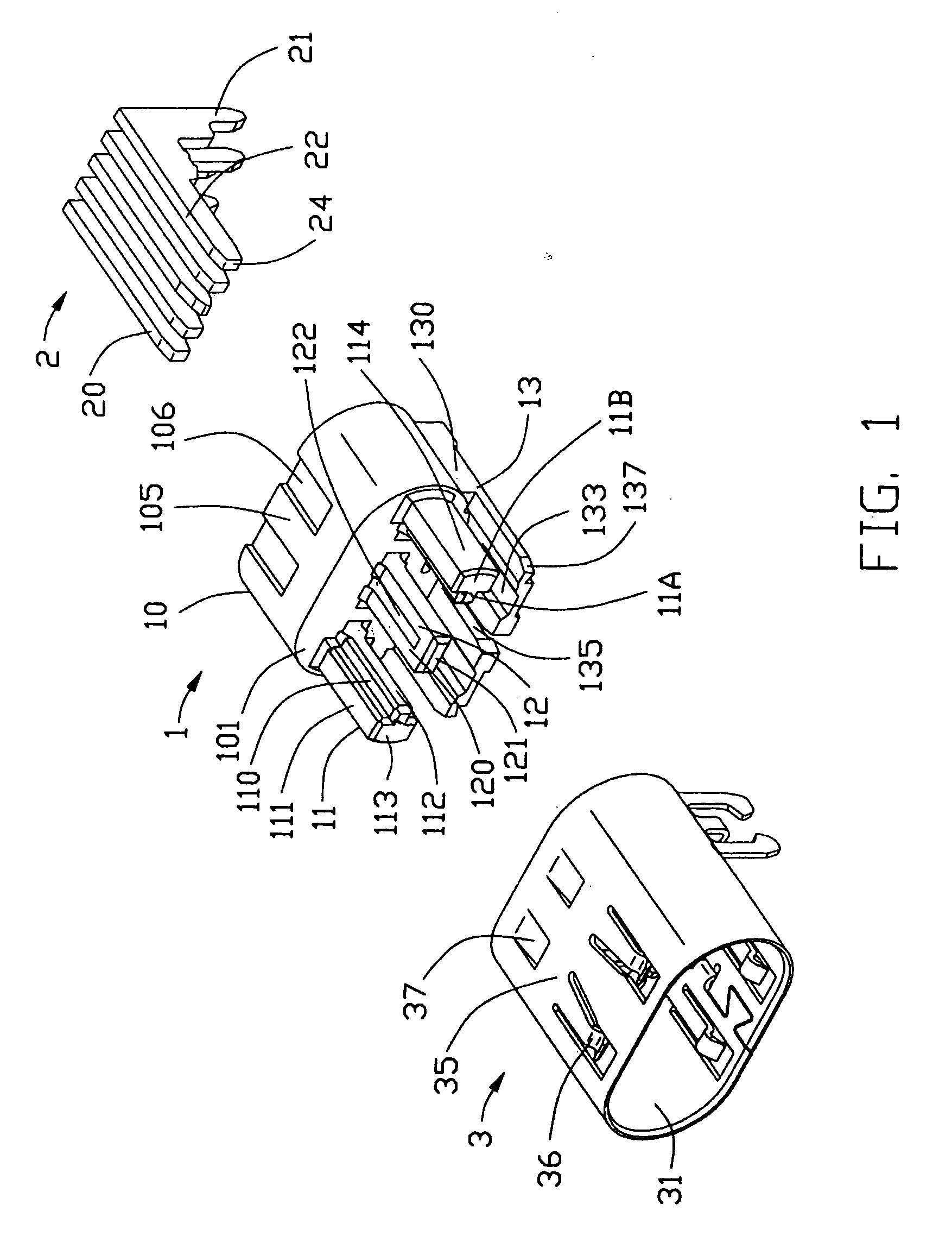
[0016] With reference to FIGS. 1-2, an electrical connector in accordance with the present invention comprises an insulative housing 1, a plurality of terminals 2 received in the insulative housing 1 and a shell 3 surrounding the insulative housing 1.

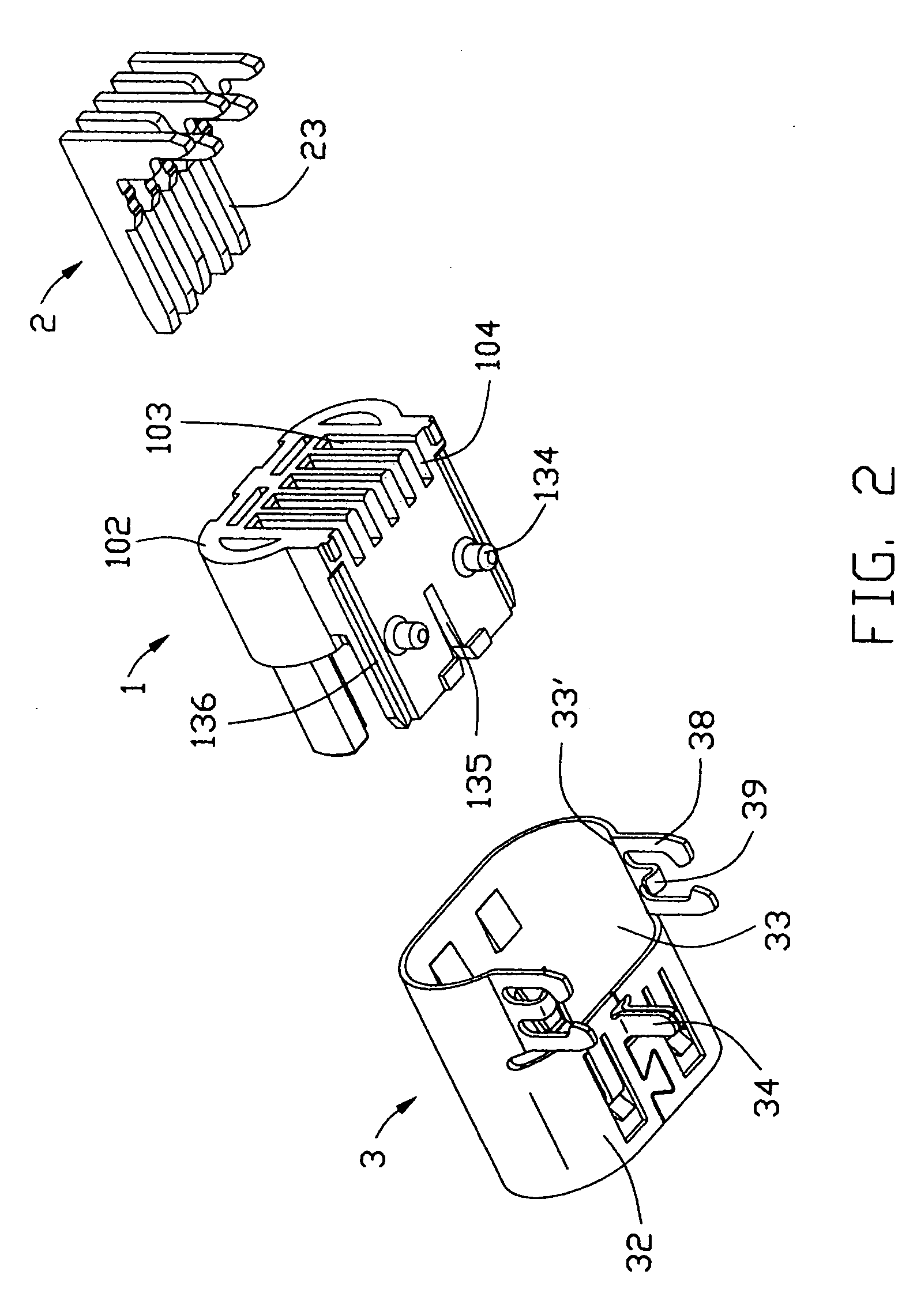
[0017] Referring to FIGS. 1-2, the insulative housing 1 has a base portion 10 with an approximately elliptic cross-section. The base portion 10 comprises an upper face 105, a front face 101 and an opposite back face 102. A plurality of receiving passageways 103 extend through the base portion 10 in a front-to-back direction. Several vertical slots 104 are defined by concaved into lower part of the back face 102, and are in communication with corresponding receiving passageways 103 respectively. The upper face 105 of the base portion 10 defines two cutouts 106 at a rear thereof. A longitudinal tongue portion 12 is formed extending forwa...


PUM


Abstract

An electrical connector includes an insulative housing (1), a plurality of contacts (2), and a shell (3) surrounding the housing. The insulative housing includes a base portion (10) with a plurality of passageways (111) extending therethrough, a tongue portion (12) extending forwardly from the base portion, and a rib (11) formed at an end of the tongue portion. A plurality of terminals are received in the passageways and extend forwardly for dividing the tongue portion into several parts. Each terminal comprises a conductive surface (22, 23). The rib extends adjacent to one of the terminals and partially protrudes beyond the conductive surface of the one of the terminals.

Description

BACKGROUD OF THE INVENTION [0001] 1. Field of the Invention [0002] The present invention generally relates to an electrical connector, and particularly relates to an electrical connector having structures for preventing deflected insertion of a complementary connector. This invention relates to a contemporaneously filed application titled “ELECTRICAL CONNECTOR HAVING IMPROVED STRUCTURE REGARDING TERMINALS” having the same applicant and the same assignee with the instant application. [0003] 2. Description of Related Arts [0004] Due to the booming development of the electronic industry, electro-consumer products become more and more popular. Miniaturization, integration and multi-function have been the inevitable trends what those products develop to. It also desires more power signals to be given to the electrical equipments, in respect that the integrated circuits have more applications, and the densities of the electrical components connected to the integrated circuits become much ...

Claims


Application Information

Patent Timeline
Patent Type & Authority Applications(United States)
IPC IPC(8): H01R13/648G01C15/00G01B11/02H01R13/631H01R13/658H01R13/6582H01R24/60
CPCH01R13/65802H01R24/60H01R13/64H01R13/6582
Inventor CHEN, ZHI-QIANGLI, XIAO-LIPENG, BING
Owner HON HAI PRECISION IND CO LTD
Why Eureka
Try Eureka