
Golf club head with alignment system

Active Publication Date: 2006-02-23
COBRA GOLF
View PDF57 Cites 9 Cited by
  • Summary
  • Abstract
  • Description
  • Claims
  • Application Information

AI Technical Summary

Benefits of technology

[0019] The weight member may be provided in the form of a bar that is attached to a rear portion of the body member. In one embodiment, the weight bar includes a slot into which one or more individual weights are adjustably positioned. Isolating the weight of the weight member further away from the body member, such as via a bar configuration, beneficially allows the designer greater control in positioning the club head center of gravity and adjusting the club head MOI. To further enhance this control, the body member may be provided with a large central cavity into which a low density core is positioned. Removing material from the central portion of the body inherently biases the club head mass and weight toward the heel and toe, which increases the MOI and makes the club more playable and forgiving. The core may also be used to dampen unwanted vibrations, increasing the golf club feel and playability.
[0021] High visibility sight lines mat be included with the club head as independent elements or as a part of another component. These sight lines have high visibility through their utilization of one or more materials that have physical properties or that have been engineered to naturally enhance, intensify, or focus light into a brighter, highly visible point or line. Two sight lines that are parallel to the strike face and perpendicular to the intended putt direction may be provided, and they may be spaced widely apart to enhance their utility in allowing the golfer to properly orient and position the golf club during use.

Problems solved by technology

However, some of these putter designs produce large putter club heads.
While these designs have improved putter performance, they have largely ignored aesthetic considerations.
An extended club body may have the deleterious effect of distracting the user.
This is particularly undesirable in golf, since golf is a very “mental” sport.

Method used


Image

  • Golf club head with alignment system
  • Golf club head with alignment system
  • Golf club head with alignment system

Examples


Embodiment Construction

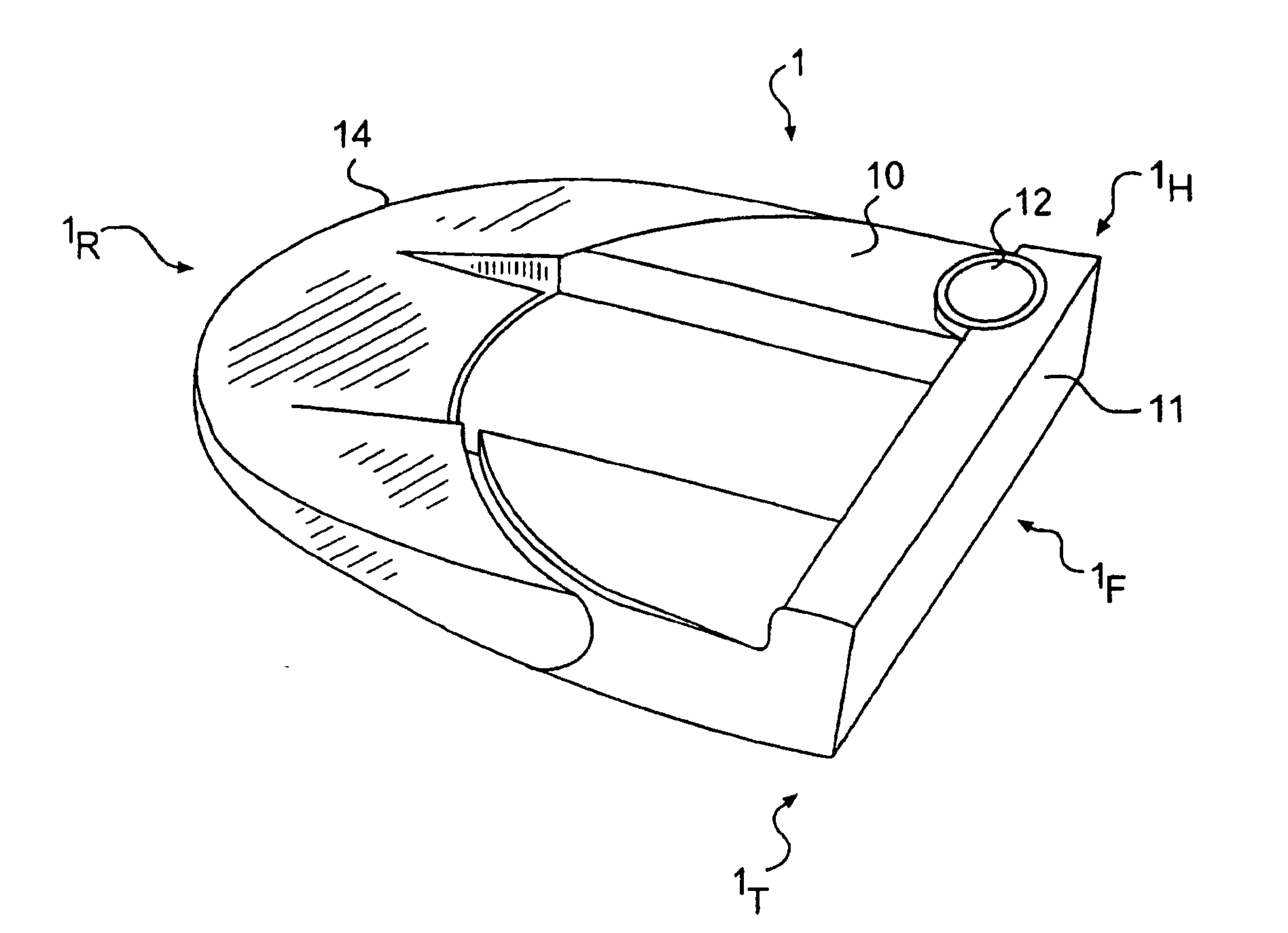
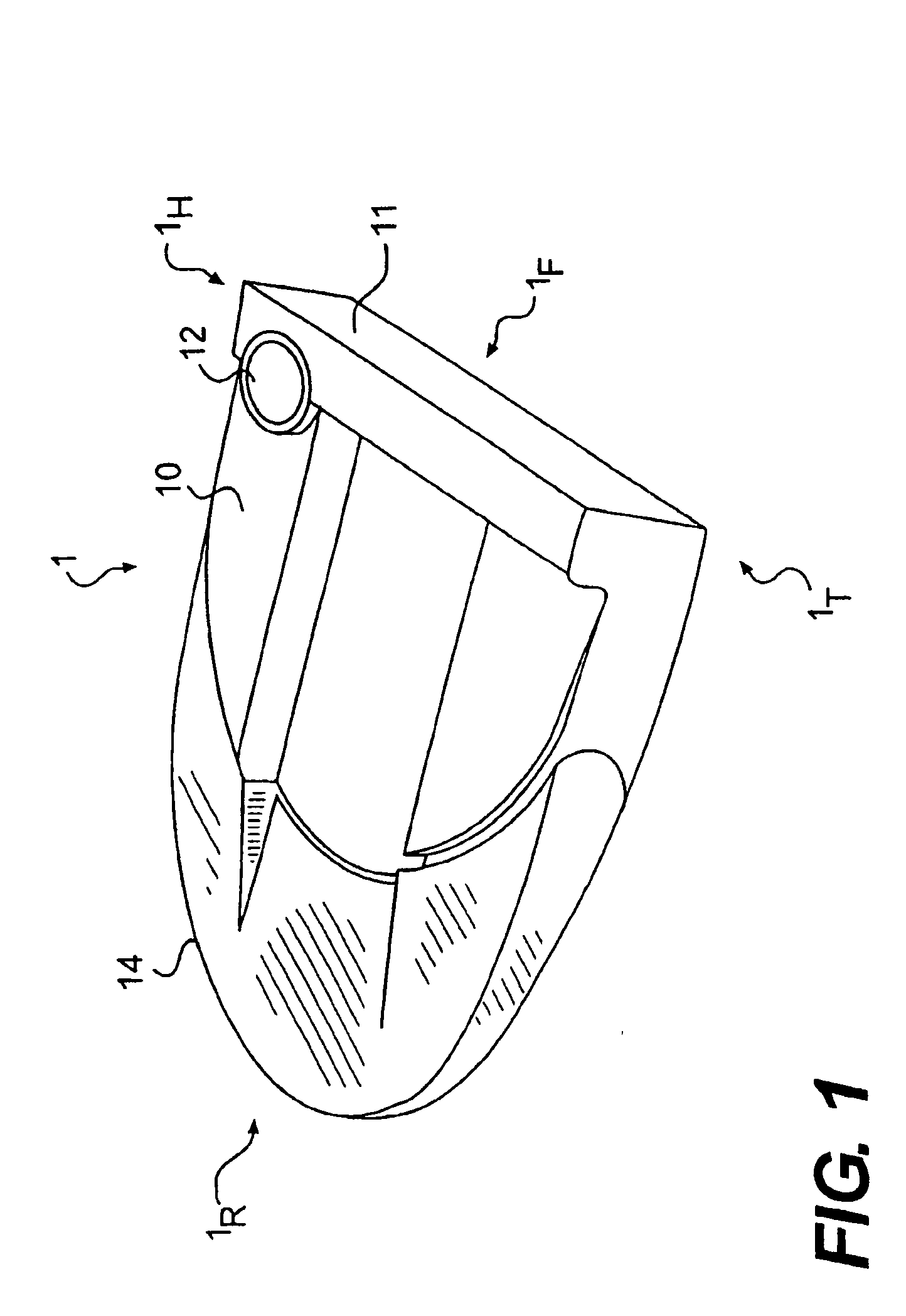
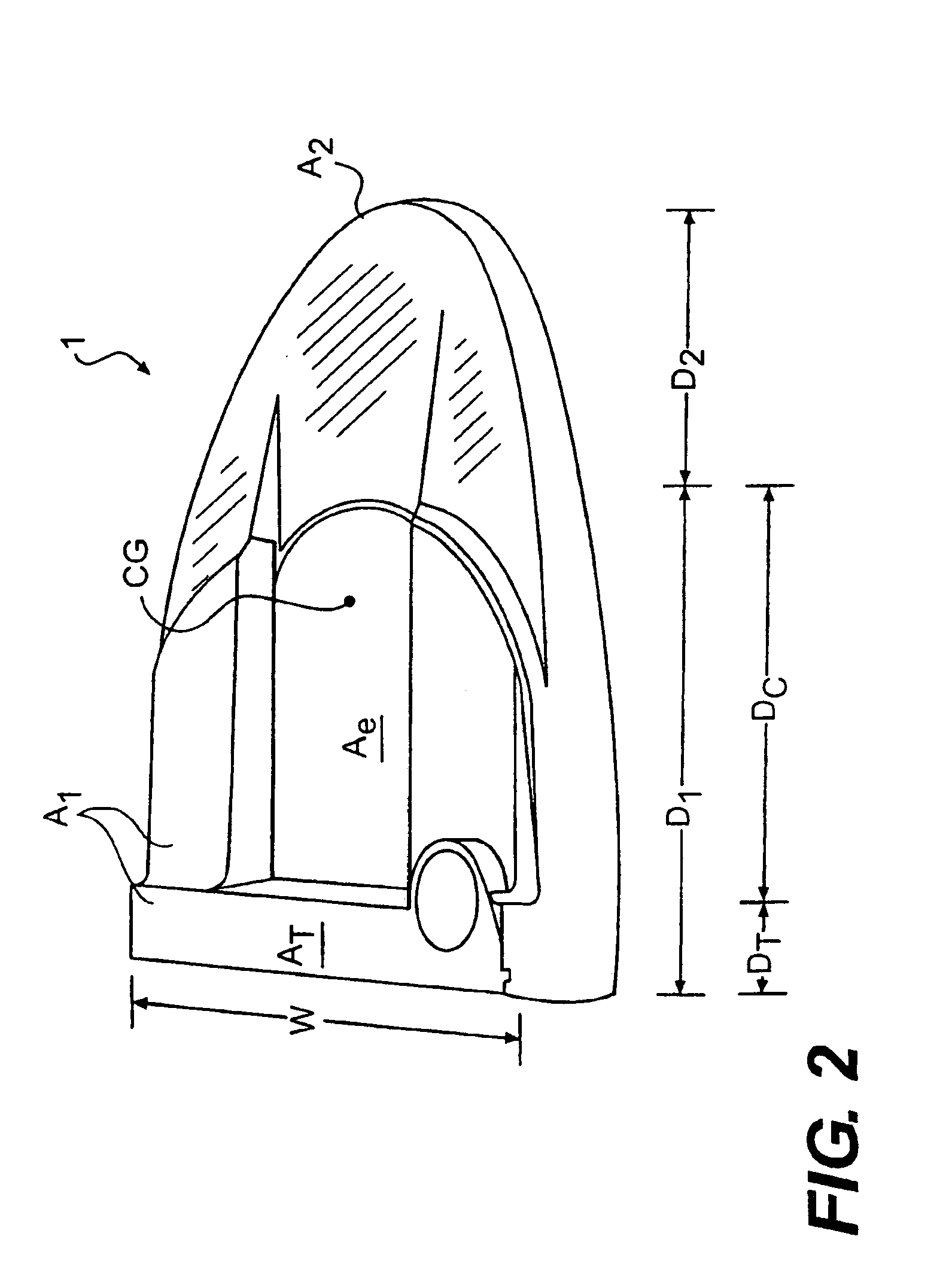
[0035]FIG. 1 shows a top view of a golf club head 1 of the present invention. The illustrated golf club is a putter. Club head 1 includes a first body member 10 and a second body member 14. First body member 10 includes a strike face 11 that contacts a golf ball during normal use. Strike face 11 may be integral with first body member 10. Alternatively, strike face 11 may be independent of and coupled to first body member 10. Preferred means of coupling include use of an adhesive, brazing, and welding. Other coupling means, such as mechanical fasteners, may also be used. Furthermore, a combination of these coupling modes could be used. First body member 10 contains a bore 12 for connecting a shaft thereto. Club head 1 has a heel 1H, a toe 1T, a face 1F, and a rear 1R.

[0036] Second body member 14 extends away from a rearward portion of first body member 10. Second body member 14 is preferably integral with first body member 10. Alternatively, second body member 14 may be independent ...


PUM

PropertyMeasurementUnit
Lengthaaaaaaaaaa
Lengthaaaaaaaaaa
Densityaaaaaaaaaa

Abstract

A golf club head is disclosed. The golf club head includes a first body member and a second body member. The first body member includes a strike face and a top portion. The second body member is coupled to the first body member and extends away from the first body member in a direction opposite the strike face. At least a top portion of the second body member is camouflaged. A preferred method of camouflage is color differentiation, wherein the second body member is darker than the first body member. Specific color values and club head geometries are also disclosed and claimed. The club head may include a body member and a weight member such as a bar that extends rearward from the body member. A cover may be included to camouflage the weight member. A separate core member and high visibility sight lines may also be provided.

Description

CROSS-REFERENCE TO RELATED APPLICATIONS [0001] This application is a continuation-in-part of U.S. patent application Ser. No. 10 / 637,530 filed on Aug. 11, 2003, now pending, which is incorporated herein by reference in its entirety.BACKGROUND OF THE INVENTION [0002] 1. Field of the Invention [0003] The present invention relates to a golf club head. In particular, the present invention relates to a golf club head having two body members, one of which being camouflaged. More particularly, the present invention relates to a golf club head having two body members of differing color. [0004] 2. Description of the Related Art [0005] There are many styles of putters, including blades, mallets, heel-toe weighted, and T-line putters. Different types of putters provide different advantages. For example, increasing the club head moment of inertia (MOI) and moving the center of gravity away from the strike face can increase the forgiveness and accuracy of putters. Heel-toe weighted putters also ...

Claims


Application Information

Patent Timeline
IPC IPC(8): A63B53/04
CPCA63B49/06A63B53/0487A63B2053/0408Y10T29/49947A63B2053/0491A63B2209/02Y10T29/49826A63B2053/0441A63B60/52A63B53/04A63B53/0441A63B53/0408A63B60/02A63B60/54
Inventor SORACCO, PETER L.RICE, SCOTT A.BEST, CHRISTOPHER B.MORRIS, THOMAS C.
Owner COBRA GOLF
Learn More