Golf putter head

a golf putter and head technology, applied in the field of golf putter head, can solve the problems of increasing the likelihood of screw loosening or adhesive deterioration, and the different parts are not so effective, and achieve the effect of improving the safety of use and reducing the risk of damag

Inactive Publication Date: 2006-02-23
DUNLOP SPORTS CO LTD
View PDF14 Cites 62 Cited by
  • Summary
  • Abstract
  • Description
  • Claims
  • Application Information

AI Technical Summary

Benefits of technology

[0044] Putter heads of all the examples and comparative example (hereinafter, also called “all the examples”) were each fabricated by combining together the head body substantially in the form of a rectangular parallelepiped and the different member having a circular section and a substantially semicircular shape, as shown in FIG. 1 and F

Problems solved by technology

Therefore, in comparison to a case where the different member is projected from the head body or extended as spaced away therefrom, the provision of the different member is not so effective as expected to increase the freedom of designing weight distribution or centroid position.
There is another problem.
In additio

Method used


Image

  • Golf putter head
  • Golf putter head
  • Golf putter head

Examples


Embodiment Construction

[0015] The preferred embodiments of the invention will hereinbelow be described with reference to the accompanying drawings.

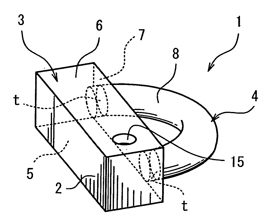
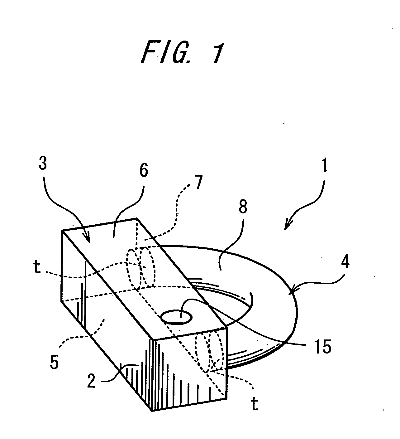
[0016]FIG. 1 is a perspective view of a golf putter head 1 according to one embodiment of the invention. The golf putter head 1 includes: a head body 3 having a face surface 2 contacting a ball at impact with the ball; and a different member 4 which is independent from the head body 3 and is fixed to a back side of the head body 3.

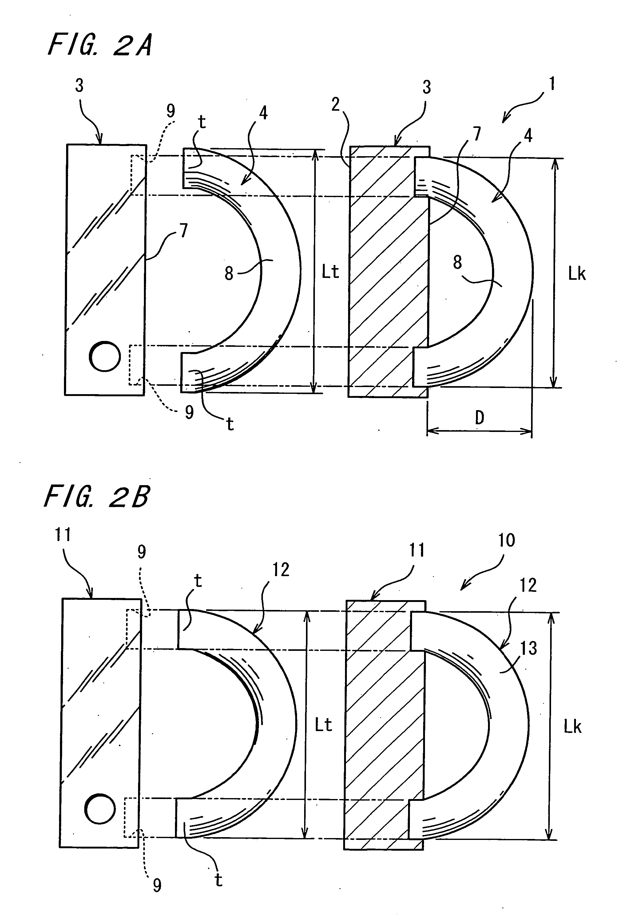
[0017] The head body 3 generally defines a rectangular parallelepiped. Besides the aforesaid face surface 2, the head body further includes: a sole surface 5 defining a bottom surface of the golf putter head 1; a top surface 6 defining an upper surface of the golf putter head 1; and a back surface 7 located on the opposite side from the face surface 2. Disposed on a heel-side of the top surface 6 is a shaft hole 15 for insertion and fixing of an unillustrated shaft.

[0018] On the other hand, the different member 4 is a bar-like memb...


PUM


Abstract

A golf putter head includes: a head body having a face surface; and a different member fixed to the head body and having a plurality of end portions as fixed portions to the head body, and a spaced extension extended between the end portions and spaced away from the head body, the different member fixed to the head body as elastically deformed by being fixed to the head body in a manner that the end portions thereof have a relative positional relation varied from that when the different member is in an independent piece state.

Description

BACKGROUND OF THE INVENTION [0001] The present invention relates to a golf putter head. [0002] Recently, a head of a composite structure combining different types of members having different specific gravities, hardnesses or the like has become predominant in the golf club head, or particularly in the putter head. For instance, Japanese Unexamined Patent Publication No. 2002-200203 has proposed a putter head wherein metal pieces having a higher specific gravity than a head body are disposed on a toe-side and a heel-side of the head, respectively, and wherein a non-metal material, such as polyurethane, is attached to a face surface of the head. OBJECT AND SUMMARY OF THE INVENTION [0003] According to the aforementioned prior art, a different member having a different specific gravity than that of the head body is embedded in the head body. Therefore, in comparison to a case where the different member is projected from the head body or extended as spaced away therefrom, the provision o...

Claims


Application Information

Patent Timeline
IPC IPC(8): A63B53/04
CPCA63B53/0487A63B59/0088A63B2053/0408A63B2053/0491A63B2053/0433A63B59/0092A63B60/54A63B60/50A63B53/0408A63B53/0433A63B60/02
Inventor SANO, YOSHINORI
Owner DUNLOP SPORTS CO LTD
Why Eureka
Try Eureka