Torque steer compensation algorithm

Inactive Publication Date: 2006-02-23
GM GLOBAL TECH OPERATIONS LLC
View PDF16 Cites 37 Cited by
  • Summary
  • Abstract
  • Description
  • Claims
  • Application Information

AI Technical Summary

Benefits of technology

[0010] Accordingly, it is an object of the present invention to provide a torque steer compensation algorithm for a motor vehicle power steering system which selectively

Problems solved by technology

The appearance of noticeable torque steer ultimately results in driver dissatisfaction.
Existing conventional methods of correcting torque steer on (hydraulic) power steered motor vehicles equipped

Method used


Image

  • Torque steer compensation algorithm
  • Torque steer compensation algorithm
  • Torque steer compensation algorithm

Examples


Embodiment Construction

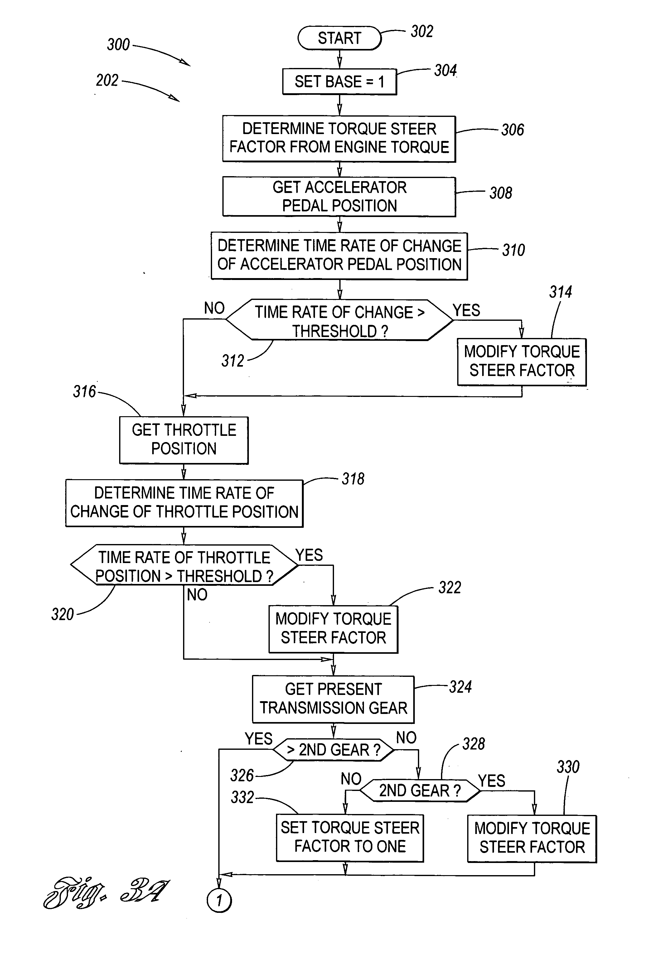
[0015] Referring now to the Drawing, wherein like reference numerals refer to like parts throughout the several views, FIGS. 2 through 3B depict aspects of a torque steer compensation algorithm 202, 300 according to the present invention.

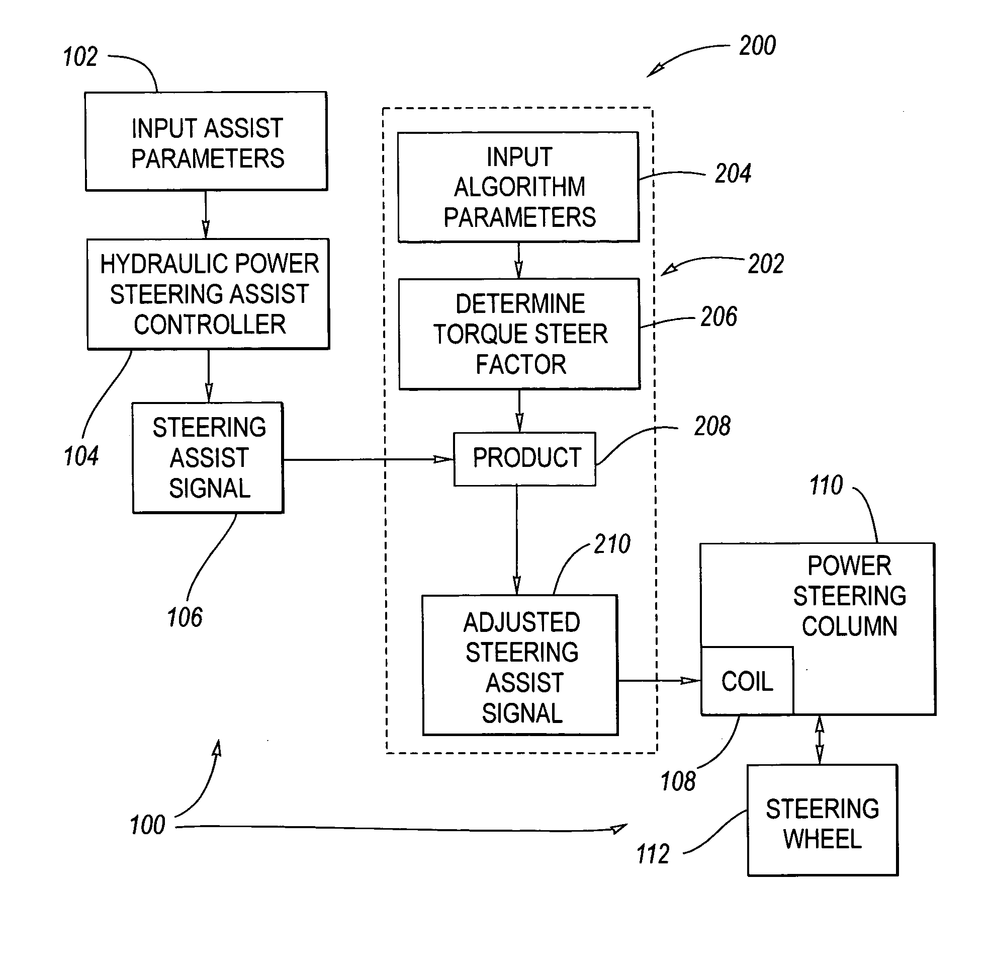
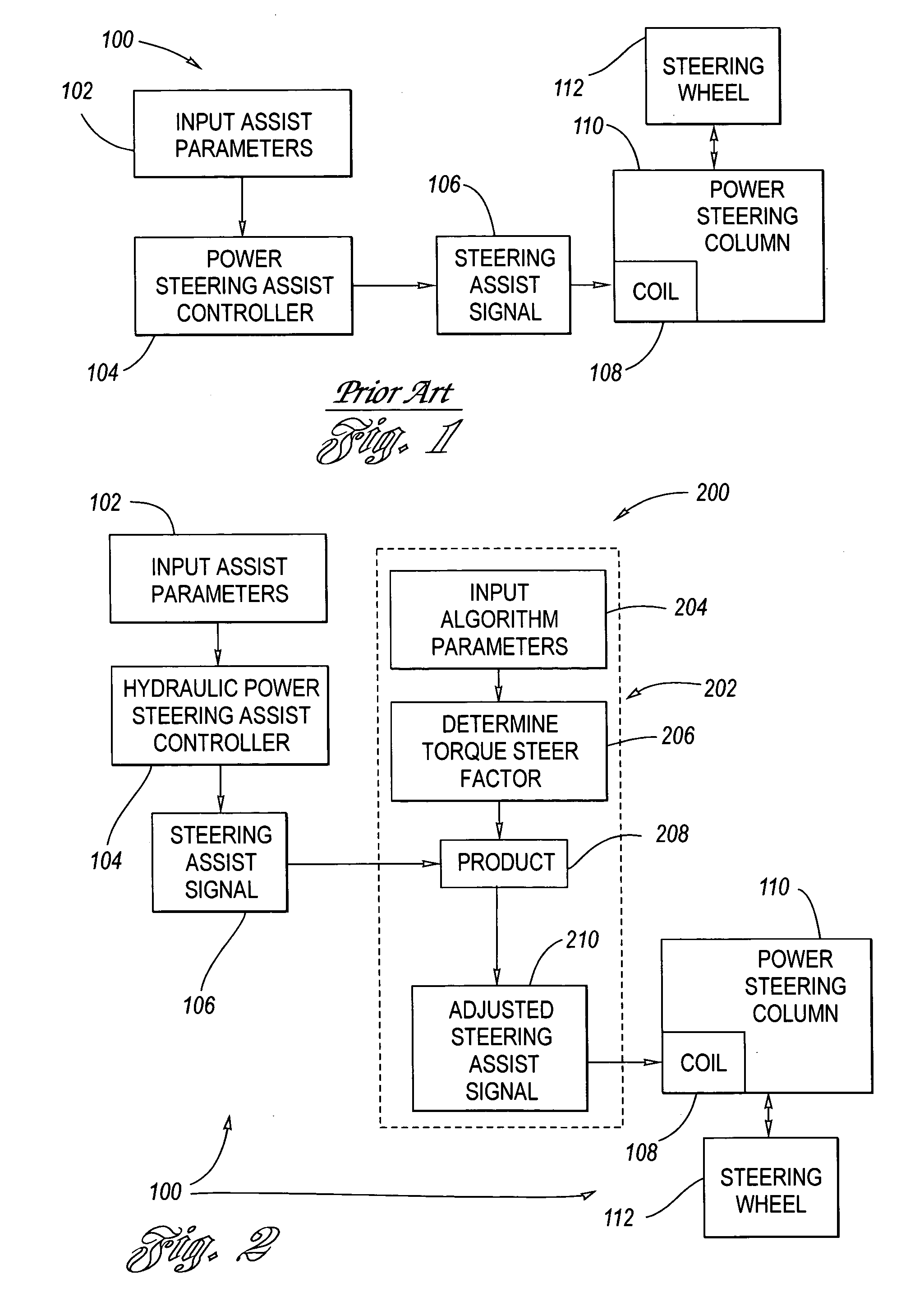
[0016]FIG. 2 depicts a power steering system 200 (commonly hydraulically based) on vehicles equipped with variable effort steering incorporating a prior art power steering system 100 and a torque steer compensation algorithm 202 according to the present invention. As discussed hereinabove with regard to FIG. 1, at Block 102, input are steering assist parameters, at least, for example, vehicle speed, which are then supplied to a conventional hydraulic power steering assist controller 104 which predicts the amount of steering assist signal to be sent to the coil 108 of the power steering column 110, according to the prior art as discussed above.

[0017] The torque steer compensation algorithm 202 according to the present invention, at Block 204, input...


PUM


Abstract

A torque steer compensation algorithm utilizing selected vehicle parameters, such as for example engine torque, accelerator pedal position, throttle position, transmission gear, and vehicle speed. Rates of change of the parameters are determined and compared to predetermined thresholds, whereby a torque steer factor is determined. The resulting torque steer factor is subsequently multiplied with a conventional, prior art predicted steering assist signal to arrive at a modified steering assist signal which is output to the coil of the steering column to reduce driver perception of torque steer at the steering wheel.

Description

TECHNICAL FIELD [0001] The present invention relates to motor vehicle power steering systems and, more particularly, to torque steer associated with motor vehicle power steering systems BACKGROUND OF THE INVENTION [0002] Torque steer experienced by a vehicle driver can be measured by the amount of steering pull, or steering wheel angle change, experienced by a driver independent of the driver's input on the steering wheel. Torque steer is usually experienced in dynamic situations in which a motor vehicle is undergoing acceleration, whether from zero speed, from a slightly higher cruising speed, or even from a much higher cruising speed, depending on the severity of the causation. The causes of torque steer vary greatly, anywhere from unequal length half-shafts, to variations in chassis, suspension or powertrain component / subsystem design, or variations in manufacture and assembly. The appearance of noticeable torque steer ultimately results in driver dissatisfaction. [0003]FIG. 1 de...

Claims


Application Information

Patent Timeline
IPC IPC(8): B62D6/00
CPCB62D5/0472B62D6/04B62D5/06
Inventor BLUNDELL, STACEY M.WEIGERT, NORMAN JOSEPHJONES, RODNEY A.D.SHAUB, PAUL S.
Owner GM GLOBAL TECH OPERATIONS LLC
Why Eureka
Try Eureka