Check patentability & draft patents in minutes with Patsnap Eureka AI!

Hardware assist for microcode tracing

Inactive Publication Date: 2006-02-23
IBM CORP
View PDF5 Cites 4 Cited by
  • Summary
  • Abstract
  • Description
  • Claims
  • Application Information

AI Technical Summary

Problems solved by technology

Many programs have a very large number of paths that may be taken, depending on the particular input parameters, and it can be very difficult to identify the source of an error.
On the other hand, the presence of such debugging features requires that the processor execute instructions that are not ordinarily used and therefore reduce the performance of the program.
Those skilled in the art will appreciate that, in some cases, extensive debugging instructions will not reduce program performance because the program performance is limited by some other factor, such as disk access.
In the particular case of microcode, the performance of the system in question is usually rather sensitive to the speed of execution because the performance of the microcode affects the execution speed of all the applications programs.
In some cases, the data might be insufficient, and in others it might be excessive.
A conditional transfer, (by inserting an AND gate keying on a debug flag in the hardware chain that carries out the transfer, or any other convenient method) would take less time, but still impose some overhead on the code.
Various modifications that impart flexibility will be evident, as will the conclusion that this approach consumes many machine cycles and runs the risk of slowing down system performance.
It has happened that the amount of debugging instructions inserted in the microcode during the initial test period caused such a slowing of performance that it was removed from the version shipped with production models of the system.
Unfortunately, difficulties with particular applications then required that software patches be written and sent to the customer to address particular issues.

Method used


Image

  • Hardware assist for microcode tracing
  • Hardware assist for microcode tracing
  • Hardware assist for microcode tracing

Examples


Embodiment Construction

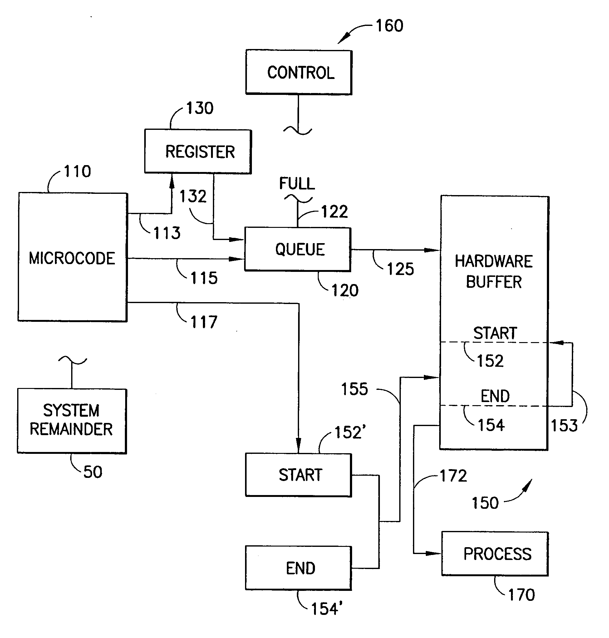
[0031]FIG. 1 illustrates a portion of a data processing system containing logic blocks related to the invention. Other conventional blocks such as memory, ALU, Input / Output, et cetera are shown schematically by block 50 which represents the remainder of a system, such a general purpose computer, special-purpose system such as a digital signal processor, etc. On the left, block 110 represents microcode that performs its usual function of running the system as well as the functions related to the invention.

[0032] The microcode contains a set of trace instructions according to the invention that consist of (one or more) write statements that transfer data from various registers, memory locations and the like (denoted generally by block 130) to hardware queue 120. Queue 120 is preferably memory mapped so that the data physically resides in a memory array, but appears to the microcode to be a

[0033] register.

[0034] Illustratively, queue 120 will be a FIFO buffer with hardware taking ov...


PUM


Abstract

Debugging microcode is facilitated by a hardware assist that takes over from the microcode the basic management of handling the data for a trace entry, thereby reducing the load on the microcode to a single micro-instruction per trace operation and thereby permitting more trace points to be included in the microcode shipped to the field.

Description

TECHNICAL FIELD [0001] The field of the invention is that of debugging microcode in data processing systems. BACKGROUND OF THE INVENTION [0002] Ever since the earliest days of programming, it has been necessary to perform tracing; i.e. feeding into the program data that are known to produce certain results and then tracing the progress of the data and intermediate results through the calculation to identify errors. [0003] In applications programming, such as an income tax calculation, the test data might be a sample income, deductions and expenses, with the contents of the program data being tested to determine if the deductions are calculated correctly [0004] Many programs have a very large number of paths that may be taken, depending on the particular input parameters, and it can be very difficult to identify the source of an error. [0005] The foregoing supports an argument for embedding extensive test facilities when a program is written, such as placing optional print statements...

Claims


Application Information

Patent Timeline
IPC IPC(8): G06F11/00
CPCG06F11/3636
Inventor CARROLL, WALKER B.JOSEPH, DOUGLAS J.TARR, GABRIEL M.
Owner IBM CORP
Features
  • R&D
  • Intellectual Property
  • Life Sciences
  • Materials
  • Tech Scout
  • Unparalleled Data Quality
  • Higher Quality Content
  • 60% Fewer Hallucinations
Learn More