Method for determining the rotation angle position of the camshaft of a reciprocating-piston engine in relation to the crankshaft

a technology of reciprocating pistons and camshafts, which is applied in the direction of machine parts testing, structural/machine measurement, instruments, etc., can solve the problems of increasing the power consumption of ec motors, affecting the accuracy of control precision, etc., and achieve the effect of accurate determination of rotation angle positions

Active Publication Date: 2006-03-02
SCHAEFFLER TECH AG & CO KG
View PDF10 Cites 33 Cited by
  • Summary
  • Abstract
  • Description
  • Claims
  • Application Information

AI Technical Summary

Benefits of technology

[0004] An object of the present invention is to provide a method for determining the rotation angle position of the camsha

Problems solved by technology

However, since the measured values are digitized and the reference point in time differs from the measurement points in time of the actuating shaft, there are measurement inaccuracies which result in the measured relative rotat

Method used


Image

  • Method for determining the rotation angle position of the camshaft of a reciprocating-piston engine in relation to the crankshaft
  • Method for determining the rotation angle position of the camshaft of a reciprocating-piston engine in relation to the crankshaft
  • Method for determining the rotation angle position of the camshaft of a reciprocating-piston engine in relation to the crankshaft

Examples


Embodiment Construction

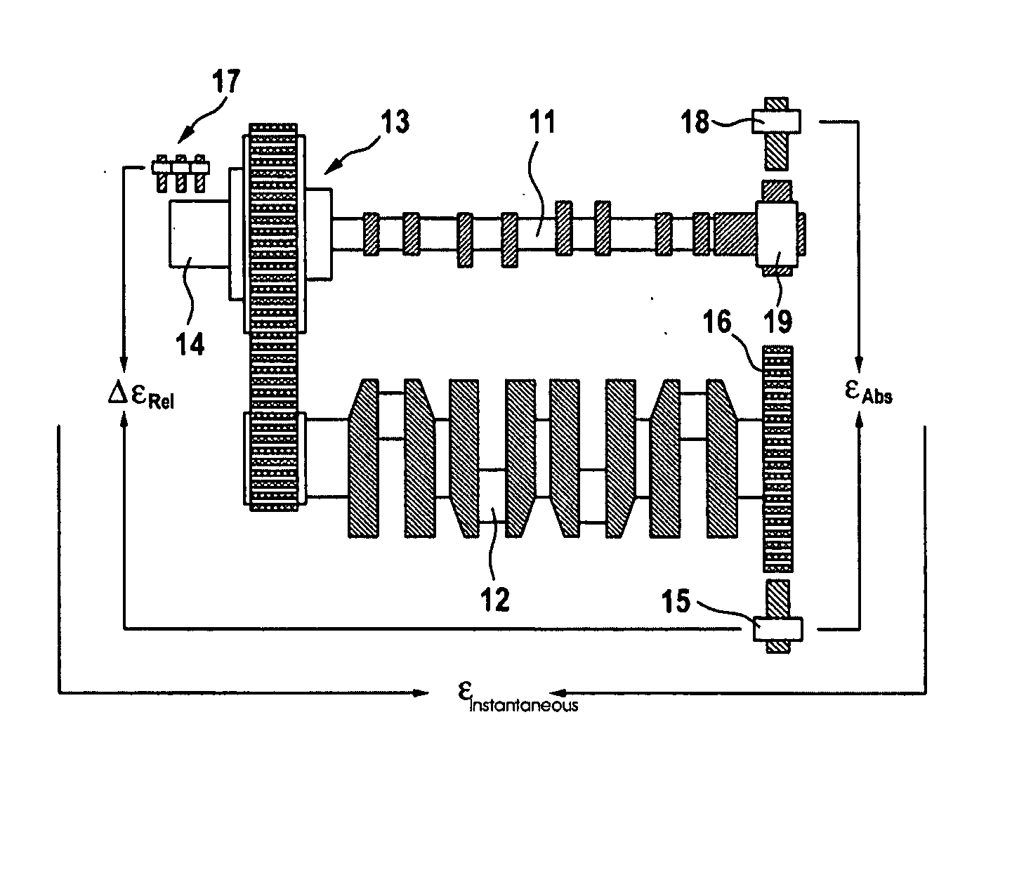
[0060] An adjusting device for adjusting the rotation angle position or phase angle of camshaft 11 of a reciprocating-piston engine in relation to crankshaft 12 has an actuating gear 13 which is designed as a three-shaft gear having a drive shaft fixedly mounted on the crankshaft, an output shaft fixedly mounted on the camshaft, and an actuating shaft in drive connection with a rotor of an actuating motor. For determining measured values for the phase angle, a measured value for the crankshaft rotation angle is determined at the crankshaft measurement points in time. In addition, a measured value for the actuating shaft rotation angle is measured at the actuating shaft measurement points in time. With the help of a known stationary gear ratio of the three-shaft gear, a value for the phase angle is determined from the measured value for the crankshaft rotation angle and the actuating shaft rotation angle.

[0061]FIG. 1 shows that an inductive sensor 15 which is provided for measuring ...


PUM

PropertyMeasurementUnit
Angleaaaaaaaaaa
Electric potential / voltageaaaaaaaaaa
Widthaaaaaaaaaa

Abstract

In a method for adjusting the rotation angle position of the camshaft of a reciprocating-piston engine in relation to the crankshaft in which the crankshaft is in drive connection with the camshaft via an actuating gear, which is designed as a three-shaft gear having a drive shaft in a fixed mounting on the crankshaft, an output shaft in a fixed mounting on the camshaft and an actuating shaft which is in drive connection with an actuating motor, a measured value for the crankshaft rotation angle is determined for at least one crankshaft measurement point in time. For at least two actuating shaft measurement points in time, a measured value for the actuating shaft rotation angle is determined digitally. For at least one reference point in time which is after the crankshaft measurement point in time and the actuating shaft measurement point in time, an estimate for the rotation angle of the actuating shaft at the reference point in time is extrapolated from at least two actuating shaft rotation angle measured values, the time difference between the actuating shaft measurement points in time and the time interval between the latest actuating shaft measurement point in time and the reference point in time. A value for the rotation angle position is determined on the basis of the estimate, the at least one crankshaft rotation angle measured value and the transmission characteristic.

Description

[0001] Priority is claimed to German Patent Application No. DE 10 2004 041 712.1, filed on Aug. 28, 2004, the entire disclosure of which is incorporated by reference herein. [0002] The present invention relates to a method for determining the rotation angle position of the camshaft of a reciprocating-piston engine in relation to the crankshaft. BACKGROUND [0003] Such methods for determining the rotation angle position of the camshaft are known from practice. A planetary gear train provided as the actuating gear is connected by its drive shaft to a camshaft gear wheel in a non-rotatable manner, the latter being mounted rotatably in relation to the camshaft and being in drive connection with a crankshaft gear wheel via a drive chain. An output shaft of the actuating gear is in drive connection with the camshaft and an actuating shaft is in drive connection with an actuating motor. When the drive shaft is stationary, the gear ratio prevailing between the actuating shaft and the output ...

Claims


Application Information

Patent Timeline
IPC IPC(8): H01H11/00
CPCF01L1/34Y10T29/49105F01L1/344F02D45/00
Inventor STORK, HOLGERDELL, HEIKONGUYEN, MINH NAM
Owner SCHAEFFLER TECH AG & CO KG
Why Eureka
Try Eureka