
Multiple steer by wire HELM system

a technology of steering system and helm, which is applied in the direction of steering initiation, special purpose vessels, vessel construction, etc., can solve the problems that the system has not been completely successful in replacing more conventional hydraulic steering system in multiple, and achieves the effects of improving safety and convenience of operation of marine craft or vessel, simplifying helm design, and simplifying manufacturing and ordering process

Active Publication Date: 2006-03-02
MARINE CANADA ACQUISITIONS INC
View PDF14 Cites 36 Cited by
  • Summary
  • Abstract
  • Description
  • Claims
  • Application Information

AI Technical Summary

Benefits of technology

[0011] The present invention has the advantage of simplifying helm design. All helms in a vessel can be physically identical. That is, no master helm is necessary, nor is a special master setup routine required to configure the master helm. This simplifies manufacturing and the ordering process for the helm manufacturer and marine craft builders.
[0012] Taking control of the marine craft is advantageously intuitive and quick with the present invention. The user can grab the wheel of any helm and start steering, without having to login or go through a transfer control routine as with prior art multiple helm systems. This improves the safety and convenience of operating the marine craft or vessel.
[0013] The aspect of the present invention wherein the fastest steered helm controls the steering of the marine craft over other helms has many advantages. The faster win scenario signifies that emergency movement is most likely with a higher rate of turn of the steering wheel. Additionally, adults tend to turn boats faster than children. The faster win scenario also advantageously ignores minor, unintentional movement from inactive helms, typically due to vibration or wind.

Problems solved by technology

However these earlier systems have not been completely successful in replacing more conventional hydraulic steering systems in multiple helm marine craft for example.

Method used


Image

  • Multiple steer by wire HELM system
  • Multiple steer by wire HELM system
  • Multiple steer by wire HELM system

Examples


Embodiment Construction

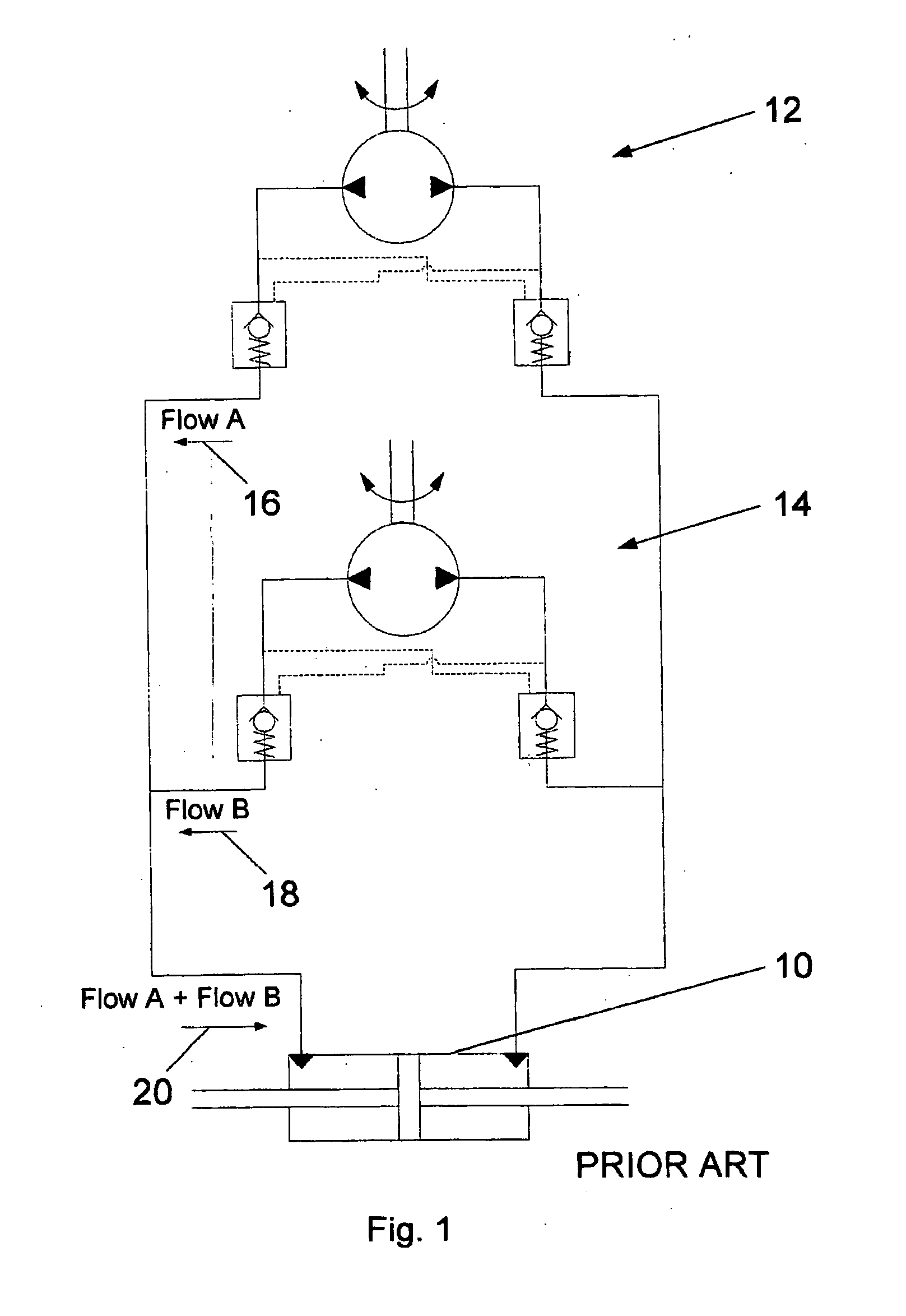
[0022] With reference to FIG. 1, a conventional marine steering system having multiple helms includes a hydraulic cylinder 10, a first hydraulic helm and a second hydraulic helm indicated generally by reference characters 12 and 14 respectively. The hydraulic cylinder 10 operates to actuate a rudder to steer the marine vessel. The fist hydraulic helm 12 is connected in parallel to the second hydraulic helm 14.

[0023] When a first vessel operator steers the first hydraulic helm 12, a flow 16 of hydraulic fluid is produced. When a second operator simultaneously steers the second hydraulic helm 14, a flow 18 is produced. A hydraulic cylinder flow 20 equals the sum of the flow 16 and the flow 18.

[0024] If the first operator turns faster than the second operator, the flow 16 is then greater than the flow 18 and dominates the flow 20 of the hydraulic cylinder 10.

[0025] This is the basic operation of a conventional multiple helm hydraulic marine steering system. One embodiment of the pre...


PUM


Abstract

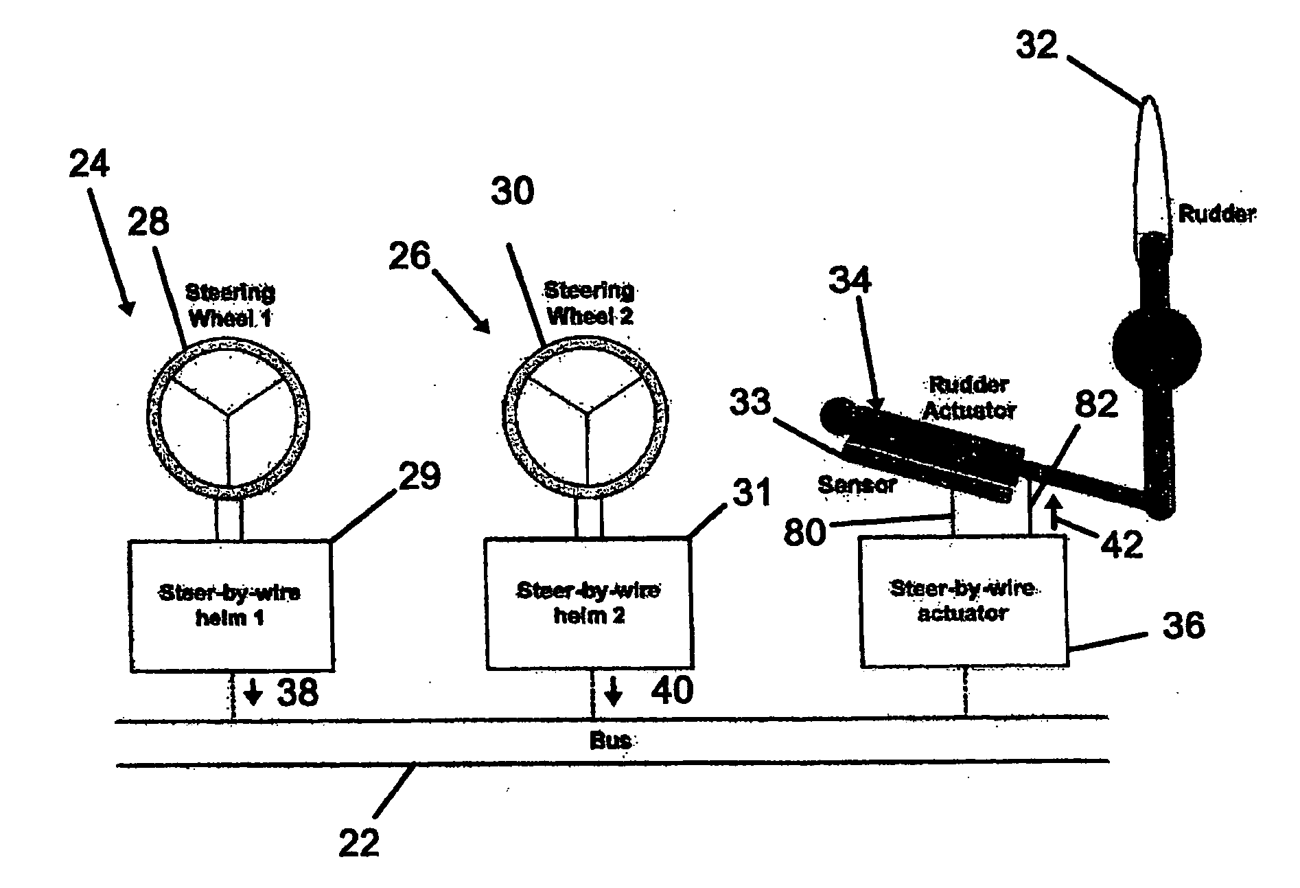
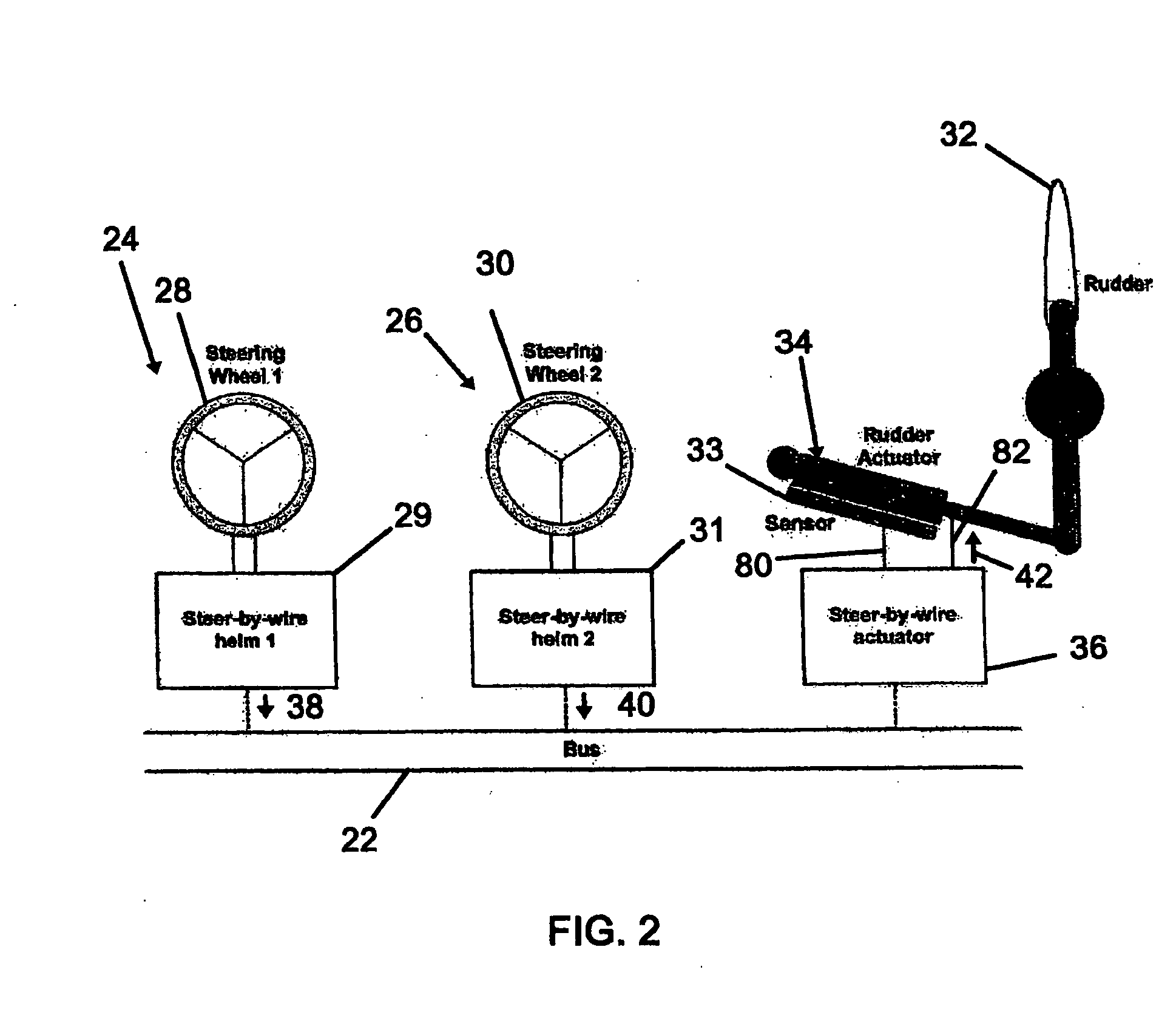
A steering apparatus for a marine craft or other vehicle having a communication bus and a plurality of helm apparatuses. Each of the helm apparatuses includes a steering device. Additionally, each of the helm apparatuses is connected to the communication bus. Each of the helm apparatuses provides helm signals indicative of incremental and decremental movement, of the steering device thereof. The helm signals are transmitted over the communication bus. The steering apparatus further includes a rudder which has an actuator and a control means for receiving each of the helm signals and which provides rudder signals to the actuator to steer the rudder in accordance with movement of the steering devices of the helm apparatuses. The control means is connected to the communication bus. Each of the rudder signals are derived from each of the helm signals from one of the helm apparatuses which is steered fastest when a plurality of the helm apparatuses is simultaneously steered.

Description

CROSS-REFERENCE TO RELATED APPLICATION [0001] This application is a continuation-in-part of copending U.S. application Ser. No. 10 / 926,327, filed on Aug. 26, 2004 and entitled STEER BY WIRE HELM, the disclosure of which is hereby incorporated by reference.BACKGROUND OF THE INVENTION [0002] This invention relates to helm steering systems and, in particular, to multiple helm steer-by-wire steering systems for marine craft or other vehicles. [0003] Conventional marine steering systems couple one or more helms to one or more rudders utilizing mechanical or hydraulic means. In smaller marine craft, cables conventionally have been used to operatively connect a helm to the rudder. Alternatively the helm has been provided with a manual hydraulic pump operated by rotation of the steering wheel. Hydraulic lines connect the helm pump to a hydraulic actuator connected to the rudder. Some marine steering systems provide a power assist via an engine driven hydraulic pump, similar to the hydraulic...

Claims


Application Information

Patent Timeline
Patent Type & Authority Applications(United States)
IPC IPC(8): B63H25/00G05D1/02
CPCB63H25/02
Inventor WONG, RAY TAT-LUNGFETCHKO, ERIC B.
Owner MARINE CANADA ACQUISITIONS INC
Learn More