
Aluminum automotive structural members

a technology of automotive structural parts and alloys, applied in the direction of metal rolling arrangements, etc., can solve the problems of affecting the quality of automotive components, affecting the service life of vehicles, etc., and achieve the effect of low cos

Inactive Publication Date: 2006-03-02
COMMONWEALTH INDS
View PDF17 Cites 20 Cited by
  • Summary
  • Abstract
  • Description
  • Claims
  • Application Information

AI Technical Summary

Benefits of technology

[0015] It is an object of the invention to provide an improved, low cost process including continuous casting and rolling to continuously produce aluminum sheet product having consistent levels of formability.
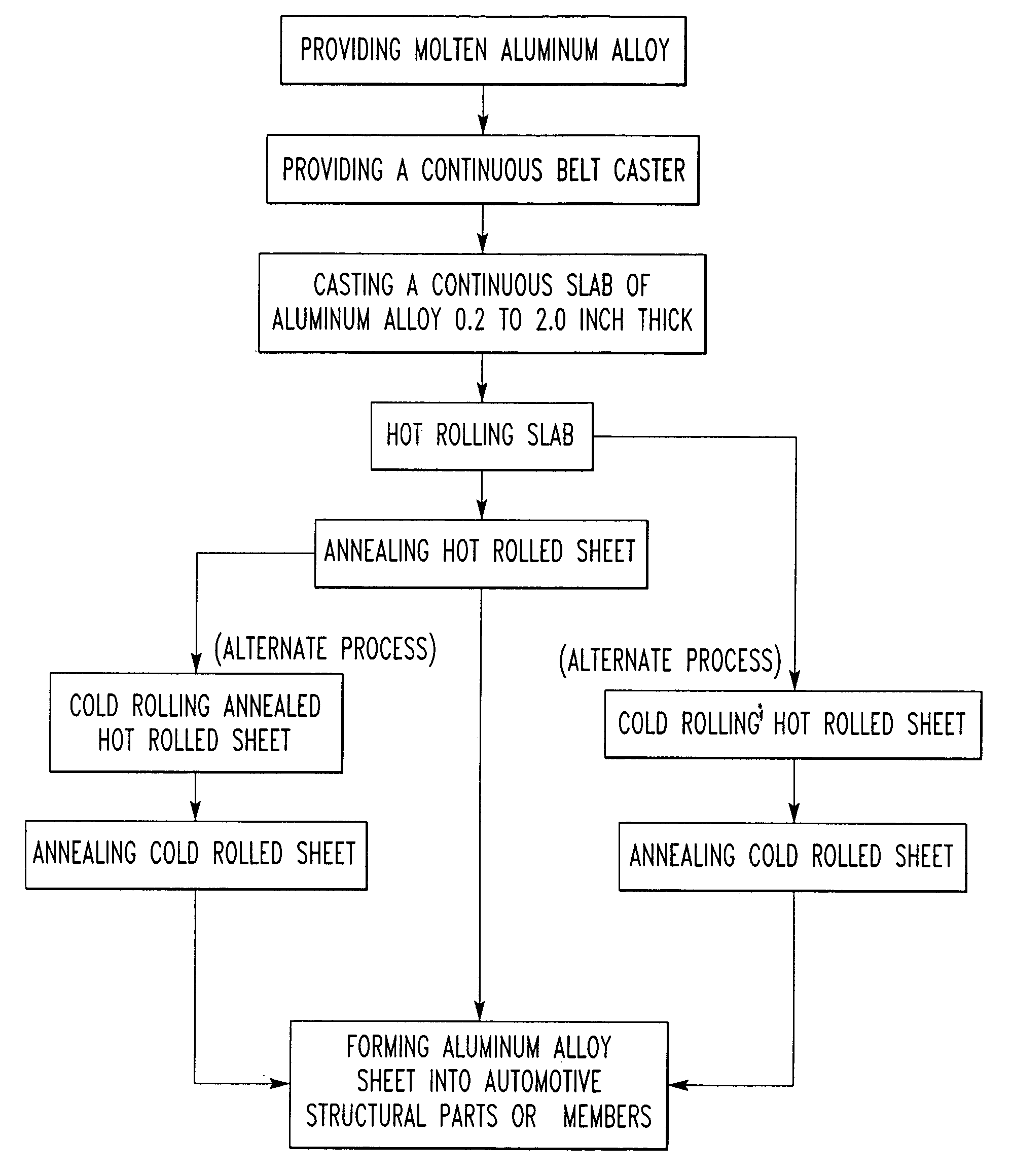
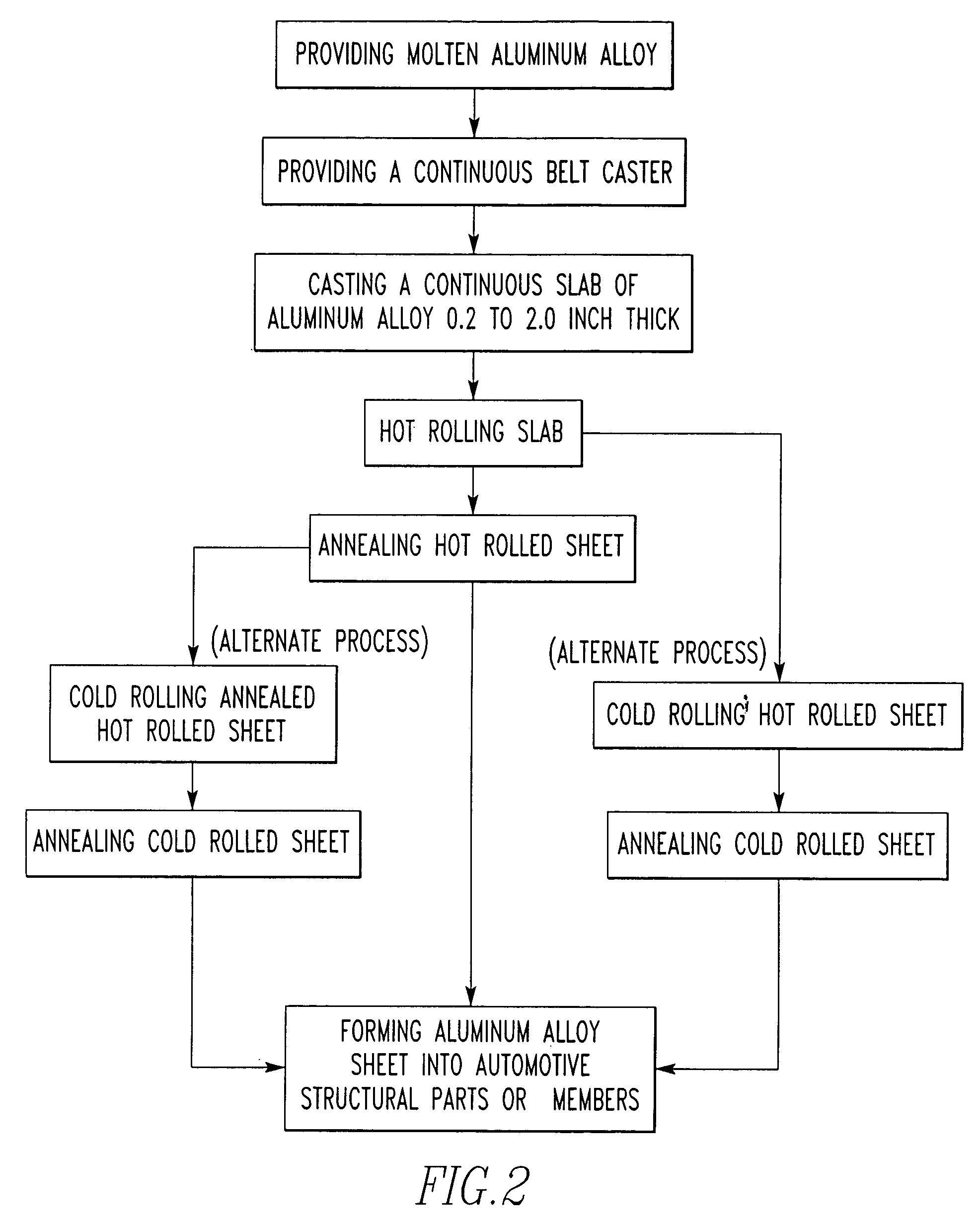
[0021] In accordance with these objects, there is provided a process for producing aluminum vehicular structural parts or members from molten aluminum alloy using a continuous caster to cast the alloy into a slab. The method comprises providing a molten aluminum alloy consisting essentially of 2.7 to 3.6 wt. % Mg, 0.1 to 0.4 wt. % Mn, 0.02 to 0.2 wt. % Si, 0.05 to 0.25 wt. % Fe, 0.1 wt. % max. Cu, 0.25 wt. % max. Cr, 0.2 wt. % max. Zn, 0.15 wt. % max. Ti, the remainder aluminum, incidental elements and impurities and providing a continuous caster such as a belt caster for continuously casting the molten aluminum alloy. The molten aluminum alloy is cast into a slab having Al—Fe, Al—Fe—Mn or Mg2Si containing intermetallic particles. The slab is rolled into a sheet product which is then annealed to provide a sheet product having a substantially uniform distribution or less striations of intermetallic particles for improved formability. Thereafter, the sheet product is formed into a vehicular structural part or member such as a panel member for a door or hood, for example, having fasteners crimped thereto.

Problems solved by technology

However, the continuous casting is not without problems.
If the alloy and processing steps are not controlled, then in the forming steps, fracture can occur and the formed parts have to be scrapped.

Method used


Image

  • Aluminum automotive structural members
  • Aluminum automotive structural members
  • Aluminum automotive structural members

Examples


example

[0063] An aluminum base alloy containing 3.267 wt. % Mg, 0.201 wt. % of Mn, 0.080 wt. % Si, 0.164 wt. % Fe, 0.020 wt. % Cu, 0.004 wt. % Cr and 0.024 wt. % Zn, was fed to a twin belt caster at a temperature of 1260° F. and solidified to produce a 0.875 inch thick slab existing the caster at a temperature of 900° F. The slab was directly fed into a three stand hot rolling mills and rolled to final gauge of 0.100 inch. The temperature of introducing the slab to the hot rolling mill was at about 820° F. and the temperature of exiting the mill was at about 520° F. The hot rolled sheet was wound into a coil. The coil was annealed in an anneal furnace at a temperature of 730° F. for 4 hours. The annealed coil was tension leveled and slit into the required width and then the coil was given a surface pretreatment and lubricated. The material had properties in the rolling direction before forming into automotive parts of: ultimate tensile strength of 32.8 ksi, yield strength of 15.5 ksi, elon...


PUM

PropertyMeasurementUnit
wt. %aaaaaaaaaa
wt. %aaaaaaaaaa
temperatureaaaaaaaaaa

Abstract

Disclosed is a method for producing aluminum vehicular structural parts or members such as from molten aluminum alloy using a continuous caster to cast the alloy into a slab. The method comprises providing a molten aluminum alloy consisting essentially of 2.7 to 3.6 wt. % Mg, 0.1 to 0.4 wt. % Mn, 0.02 to 0.2 wt. % Si, 0.05 to 0.30 wt. % Fe, 0.1 wt. % max. Cu, 0.25 wt. % max. Cr, 0.2 wt. % max. Zn, 0.15 wt. % max. Ti, the remainder aluminum, incidental elements and impurities and providing a continuous caster such as a belt caster, block caster or roll caster for continuously casting the molten aluminum alloy. The molten aluminum alloy is cast into a slab which is rolled into a sheet product and then annealed. The sheet has an improved distribution of intermetallic particles (Al—Fe, Al—Fe—Mn or Mg2Si) and improved formability. Thereafter, the sheet product is formed into the vehicular structural part or member with sufficient strength and formability required by automotive industry.

Description

BACKGROUND OF THE INVENTION [0001] This invention relates to aluminum alloy vehicular structural parts or members and more particularly, it relates to a method of casting aluminum alloy into sheet having good forming characteristics and to forming the sheet into vehicular structural parts or members such as dash panel, floor panel, door panel, window trim, radio bracket, reinforcements for panels, etc. [0002] In many instances, continuous casting of molten aluminum into slab utilizing twin belt, twin roll or block casters is favored over DC casting because continuous casting can result in substantial energy savings and total conversion cost savings compared to the DC cast method. In the continuous casting process, molten metal is continuously introduced to an advancing mold and a slab is produced which may be continuously formed into a sheet product which is collected or wound into a coil. However, the continuous casting is not without problems. For example, it has been discovered t...

Claims


Application Information

Patent Timeline
Patent Type & Authority Applications(United States)
IPC IPC(8): C22F1/04
CPCB22D11/003C22F1/04C22C21/08B22D11/0605B21B3/00C22F1/05
Inventor LI, ZHONGPLATEK, PAUL
Owner COMMONWEALTH INDS
Learn More