Microfluidic electrophoresis chip having flow-retarding structure

a microfluidic electrophoresis and flow-retarding technology, applied in the direction of fluid pressure measurement, liquid/fluent solid measurement, peptide measurement, etc., can solve the problem of adversely affecting the detection limit (lod), and achieve the effect of reducing electrokinetic flow instabilities and high hydraulic resistan

Inactive Publication Date: 2006-03-02
THE BOARD OF TRUSTEES OF THE LELAND STANFORD JUNIOR UNIV
View PDF1 Cites 36 Cited by
  • Summary
  • Abstract
  • Description
  • Claims
  • Application Information

AI Technical Summary

Benefits of technology

[0012] In another aspect, the present invention is directed to a method of reducing electrokinetic flow instabilities during electrophoresis of a sample across a conductivity gradient in a main separation channel of a microfluidic electrophoresis chip. The method calls for providing a high hydraulic resistance region in the main separation channel between an upstream portion and a downstream portion, introducing first and second buffers on different sides of the high hydraulic resistance region, introducing a sample into the upstream portion, and then applying a voltage to cause the sample to separate and migrate in the direction of the downstream portion.

Problems solved by technology

One drawback of microchannels is that the depth dimensions of etched channels (typically 10-20 μm deep) provide a short line-of-sight-integration length for optical detectors, and this adversely affects their limit of detection (LOD).

Method used


Image

  • Microfluidic electrophoresis chip having flow-retarding structure
  • Microfluidic electrophoresis chip having flow-retarding structure
  • Microfluidic electrophoresis chip having flow-retarding structure

Examples


Embodiment Construction

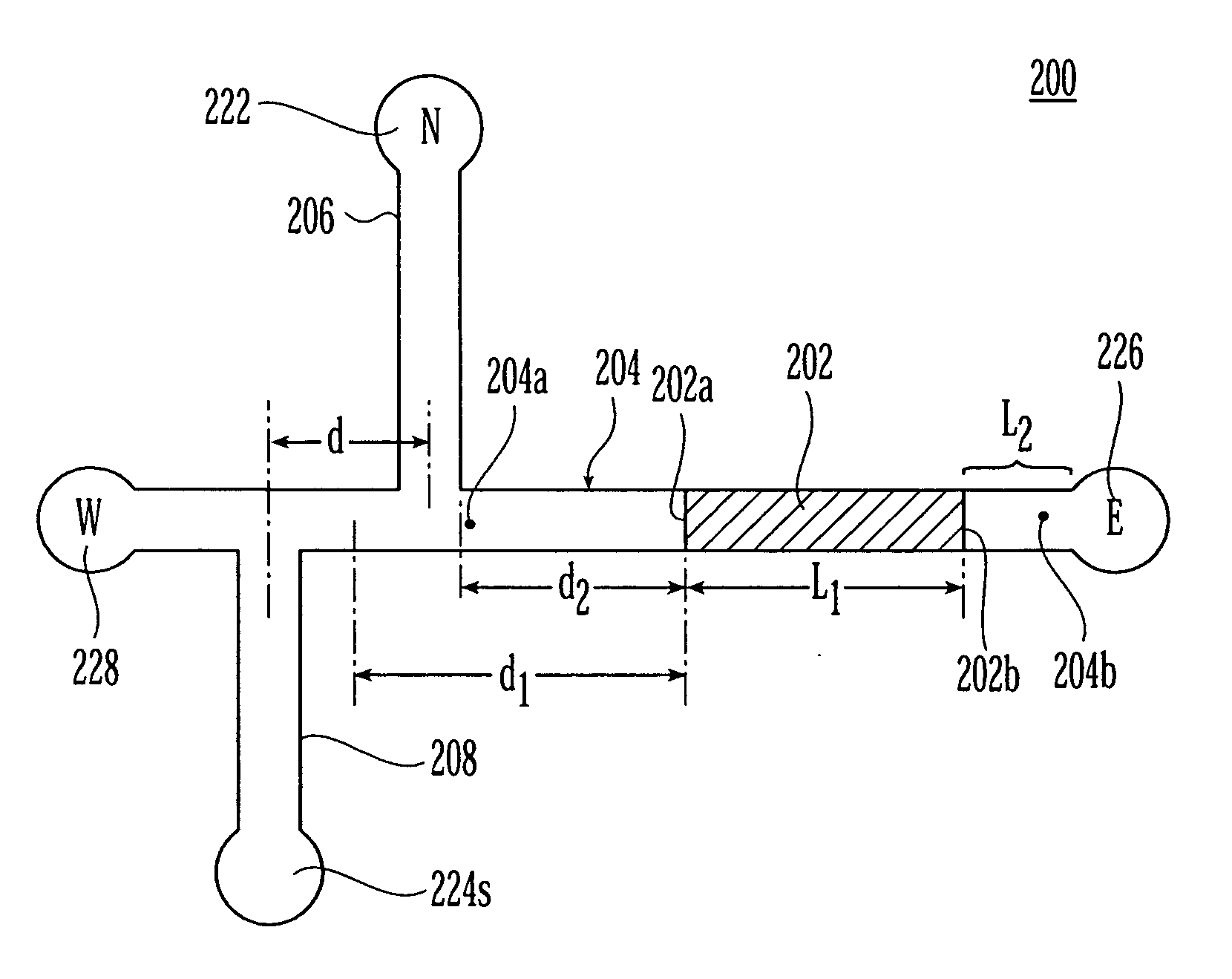
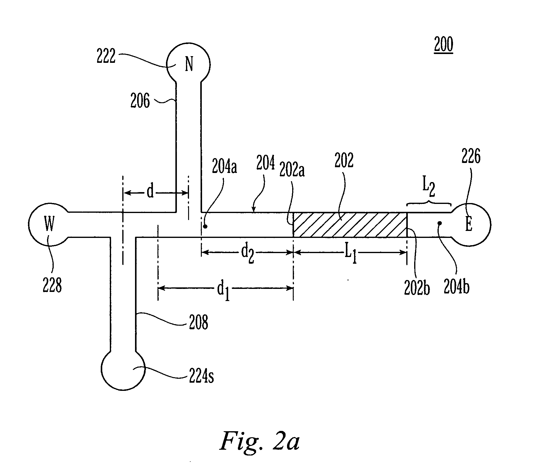
[0025]FIG. 2a shows a microchip 200 in accordance with the present invention. The microchip 200 has a hydraulic resistance-providing structure (HRPS) 202 of length L1 along the horizontal, main separation channel 204. The HRPS 202 is positioned such that an ‘open’ channel extends on either side. Thus, the HRPS 202 has an upstream interface 202a facing an upstream portion 204a of the main separation channel 204 and a downstream interface 202b facing a downstream portion 204b of the main separation channel 204. As seen in FIG. 1, the downstream portion 204b extends for some non-zero length L2.

[0026] Connected to the main separation channel at a first channel center point is a first, or north, side channel 206. A second, or south, side channel 208 is connected to the main separation channel 204 at a second channel center point. In a preferred embodiment, the first and second channel center points are spaced apart from each other by a distance d and so the microchip has a “double-T” co...


PUM

PropertyMeasurementUnit
lengthaaaaaaaaaa
lengthaaaaaaaaaa
depth h1aaaaaaaaaa

Abstract

A capillary electrophoresis device and separation protocol uses a hydraulic resistance-providing structure (HRPS) in the main separation channel to separate the divide the main separate channel into an upstream portion and a downstream portion. The HRPS may take the form of a porous plug, or a solid plug provided with at least one shallow channel. A sample separates and migrates through the porous structure or the shallow channel, upon application of a voltage difference between the upstream and downstream sides. Among other things, the HRPS helps reduce electrokinetic flow in the presence of conductivity gradients and facilitates robust, high-gradient on-chip field amplified sample stacking. The HRPS also enables the use of a pressure-injection scheme for the introduction of a high conductivity gradient in a separation channel and thereby avoids flow instabilities associated with high conductivity gradient electrokinetics. The approach also allows for the suppression of electroosmotic flow (EOF) and benefits from the associated minimization of sample dispersion caused by non-uniform EOF mobilities. An injection procedure employing a single pressure-flow high-conductivity buffer injection step followed by standard high voltage control of electrophoretic fluxes of sample, may be employed.

Description

GOVERNMENT RIGHTS [0001] A portion of the work associated with the present invention was funded by DARPA grant F30602-00-2-0609. The U.S. Government may have rights to the present invention.FIELD OF THE INVENTION [0002] The present invention is directed to microfluidic devices for carrying out electrophoresis. More particular, the present invention is directed to devices and methods designed for Field Amplified Sample Stacking (FASS) applications and their integration with electrophoretic separations. BACKGROUND [0003] On-chip electrophoresis devices offer reduced sample volumes, rapid analysis time, and ease of automation. One drawback of microchannels is that the depth dimensions of etched channels (typically 10-20 μm deep) provide a short line-of-sight-integration length for optical detectors, and this adversely affects their limit of detection (LOD). One way of improving LOD is to integrate an on-line preconcentration process for sample analytes. Sample preconcentration offers h...

Claims


Application Information

Patent Timeline
Patent Type & Authority Applications(United States)
IPC IPC(8): C07K1/26G01N27/447
CPCG01N27/44791
Inventor SANTIAGO, JUAN G.JUNG, BYOUNGSOKBHARADWAJ, RAJIV
Owner THE BOARD OF TRUSTEES OF THE LELAND STANFORD JUNIOR UNIV
Why Eureka
Try Eureka