Driver blade with auxiliary combustion chamber for combustion powered fastener-driving tool

a technology of auxiliary combustion chamber and fastener, which is applied in the direction of rotary clutches, portable drilling machines, fluid couplings, etc., can solve the problems of increasing the firing power of the tool, and achieve the effects of reducing the overall tool weight, and reducing energy consumption

Inactive Publication Date: 2006-03-02
ILLINOIS TOOL WORKS INC
View PDF17 Cites 3 Cited by
  • Summary
  • Abstract
  • Description
  • Claims
  • Application Information

AI Technical Summary

Benefits of technology

[0008] The above-listed needs are met or exceeded by the present driver blade, preferably provided associated with a piston. The driver blade is generally hollow, which reduces weight, thus reducing overall tool weight and also requiring less energy to return to the prefiring position. In addition, the substantially hollow configuration increases the volume of the combustion chamber, thus increasing the firing power of the tool. A lower end of the driver blade is provided with a solid cross-section for facilitating the fastener driving operation.

Problems solved by technology

In addition, the substantially hollow configuration increases the volume of the combustion chamber, thus increasing the firing power of the tool.

Method used


Image

  • Driver blade with auxiliary combustion chamber for combustion powered fastener-driving tool
  • Driver blade with auxiliary combustion chamber for combustion powered fastener-driving tool
  • Driver blade with auxiliary combustion chamber for combustion powered fastener-driving tool

Examples


Embodiment Construction

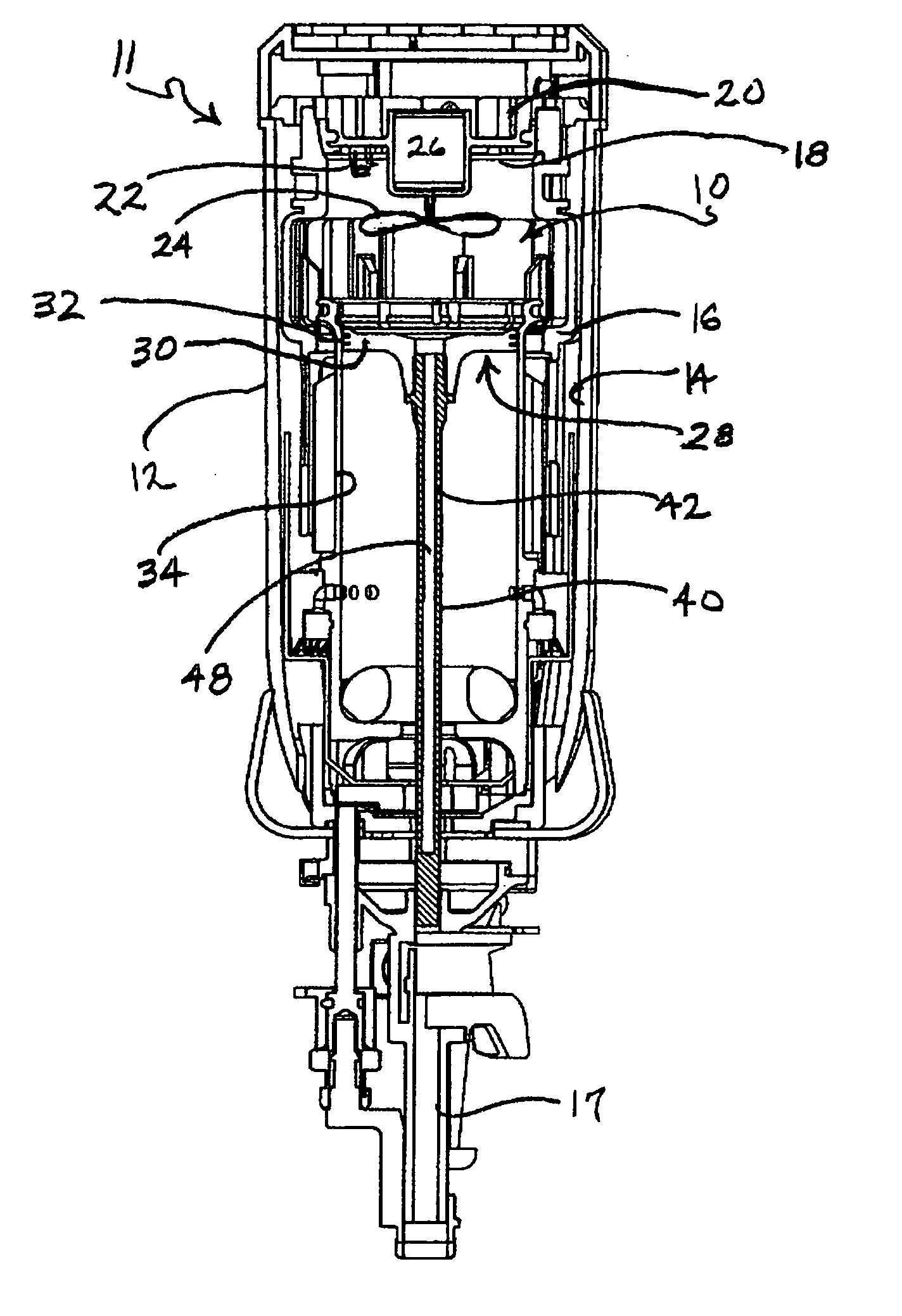
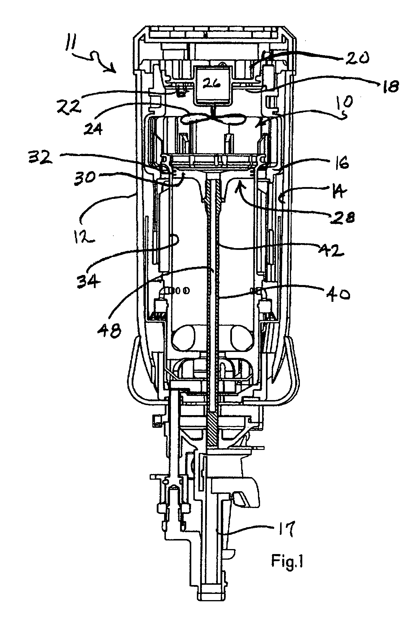
[0014] Referring now to FIG. 1, a combustion chamber for a combustion-powered fastener-driving tool incorporating the present invention is generally designated 10. The present combustion chamber 10 and associated components is suitable for use in any type of combustion-powered fastener-driving tool, generally designated 11, including but not limited to the general type described in detail in the patents listed above and incorporated by reference in the present application. A housing 12 of the tool 11 encloses the combustion chamber 10 within a housing main chamber 14.

[0015] The combustion chamber 10 is defined on the sides by a generally cylindrical reciprocating valve sleeve 16, which as is known in the art, reciprocates between an open or exhaust position (shown here) when the tool is at rest or between firings, and a closed or combustion position just prior to and during the firing portion of the tool cycle. The closed position is achieved by pressing the tool against a workpiec...


PUM

PropertyMeasurementUnit
total lengthaaaaaaaaaa
lengthaaaaaaaaaa

Abstract

A driver blade for use in a combustion-powered fastener-driving tool includes an elongate tubular body having a combustion end and a driving end, the combustion end being configured for attachment to a piston, and the driving end having a substantially solid cross-section. The tubular body is in fluid communication with a tool combustion chamber.

Description

BACKGROUND [0001] The present invention relates generally to fastener-driving tools used to drive fasteners into workpieces, and specifically to combustion-powered fastener-driving tools, also referred to as combustion tools. [0002] Combustion-powered tools are known in the art, and one type of such tools, also known as IMPULSE® brand tools for use in driving fasteners into workpieces, is described in commonly assigned patents to Nikolich U.S. Pat. Re. No. 32,452, and U.S. Pat. Nos. 4,522,162; 4,483,473; 4,483,474; 4,403,722; 5,197,646; 5,263,439 and 6,145,724, all of which are incorporated by reference herein. Similar combustion-powered nail and staple driving tools are available commercially from ITW-Paslode of Vernon Hills, Ill. under the IMPULSE®[ ] and PASLODE® brands. [0003] Such tools incorporate a generally pistol-shaped tool housing enclosing a small internal combustion engine. The engine is powered by a canister of pressurized fuel gas, also called a fuel cell. A battery-p...

Claims


Application Information

Patent Timeline
Patent Type & Authority Applications(United States)
IPC IPC(8): B25C1/14
CPCB25C1/08F16D33/20B27F7/05B25D9/02
Inventor PANASIK, CHERYL L.TUCKER, KEVIN M.KOLODZIEJ, NORBERT K.GONG, YONGPINGFISCHER, ROBERT B.
Owner ILLINOIS TOOL WORKS INC
Why Eureka
Try Eureka