Metal base wiring board for retaining light emitting elements, light emitting source, lightning apparatus, and display apparatus

a technology of metal base wiring and light emitting elements, applied in the direction of semiconductor devices for light sources, light and heating devices, printed circuit non-printed electric components association, etc., can solve the problems of reduced light emitting efficiency or short life of leds, temperature rise as leds emit light, and conventional metal base wiring boards provide insufficient heat dissipation for a high optical power output, etc., to achieve the effect of releasing hea

Inactive Publication Date: 2006-03-02
PANASONIC CORP
View PDF3 Cites 54 Cited by
  • Summary
  • Abstract
  • Description
  • Claims
  • Application Information

AI Technical Summary

Benefits of technology

[0057] With the above-described construction, when the light emitting elements generate heat as they emit light, the heat is transmitted to the metal base on the rear side of the insulation substrate via the heat conductive member. This enables the...

Problems solved by technology

The increase in temperature leads to reduction of light emitting efficiency or short life of LEDs.
However, when a larger number of LEDs are mounted to increase the optical power output per unit area, the spacin...

Method used


Image

  • Metal base wiring board for retaining light emitting elements, light emitting source, lightning apparatus, and display apparatus
  • Metal base wiring board for retaining light emitting elements, light emitting source, lightning apparatus, and display apparatus
  • Metal base wiring board for retaining light emitting elements, light emitting source, lightning apparatus, and display apparatus

Examples


embodiment 1

[0090] The present embodiment will explain an LED light source that includes a metal base wiring board having recesses in a front surface thereof, where light emitting elements are mounted in the recesses. The metal base wiring board includes an insulation substrate composed of a plurality of insulation layers. The recesses are formed to pass through the insulation layers in the thickness direction of the insulation substrate downward, leaving part of the layers intact.

1. Construction of LED Light Source

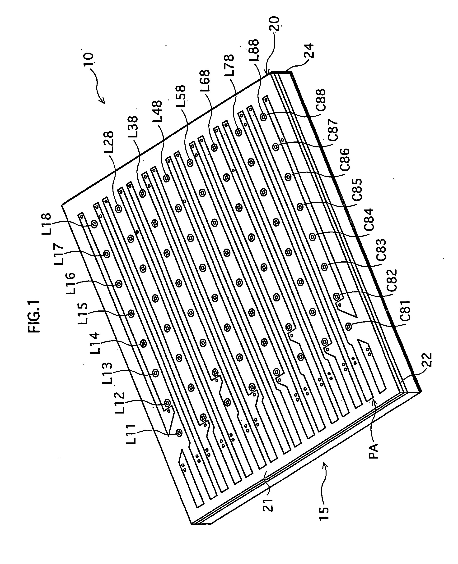
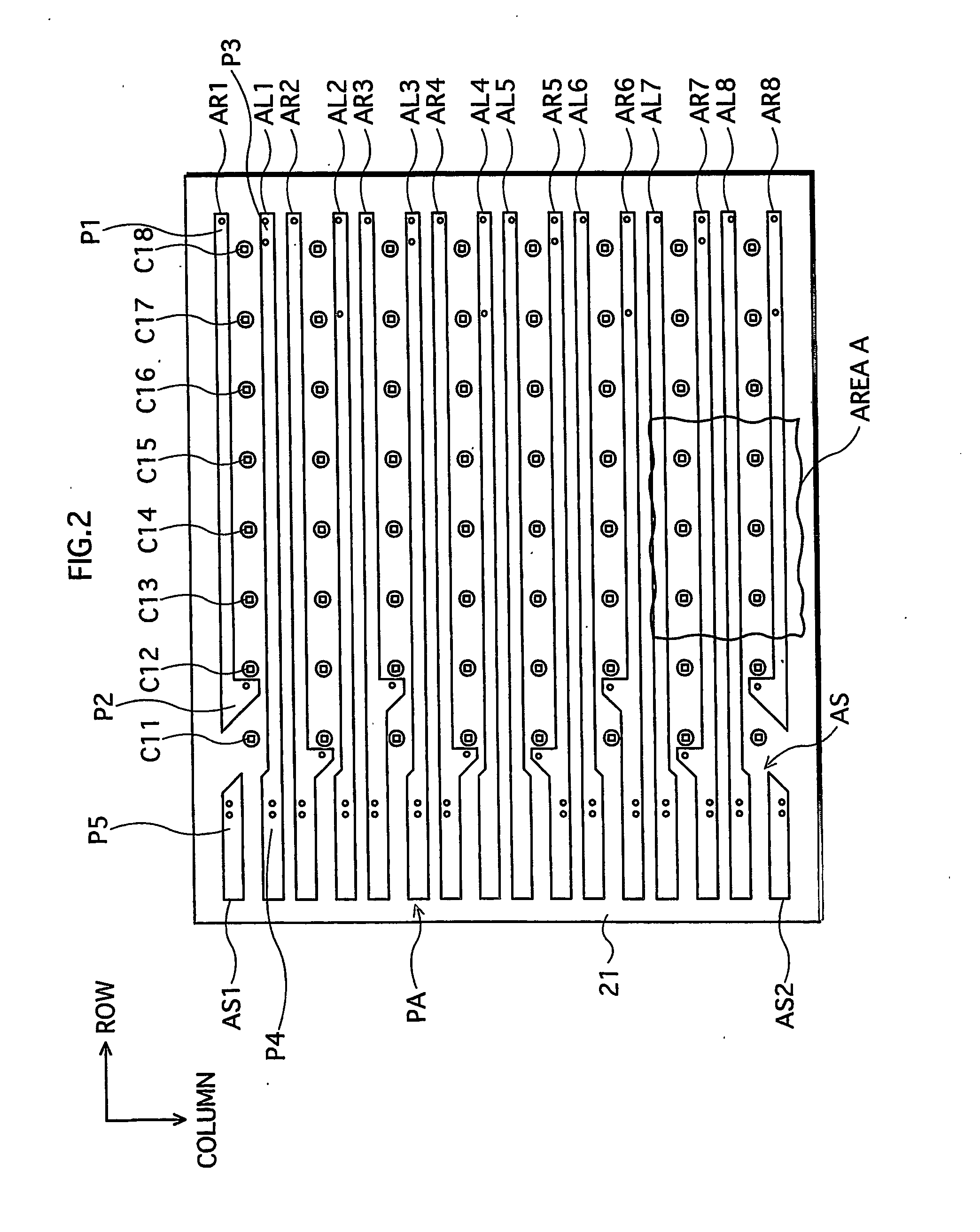
[0091]FIG. 1 is a perspective view of an LED light source in Embodiment 1.

[0092] An LED light source 10 (corresponding to “light emitting source” of the present invention) includes: a metal base wiring board 15 (corresponding to “metal base wiring board for retaining light emitting elements” of the present invention) whose upper (front) surface has a plurality of recesses that are circular in a plane view; and LED bare chips which are mounted in the recesses on the bottom faces t...

embodiment 2

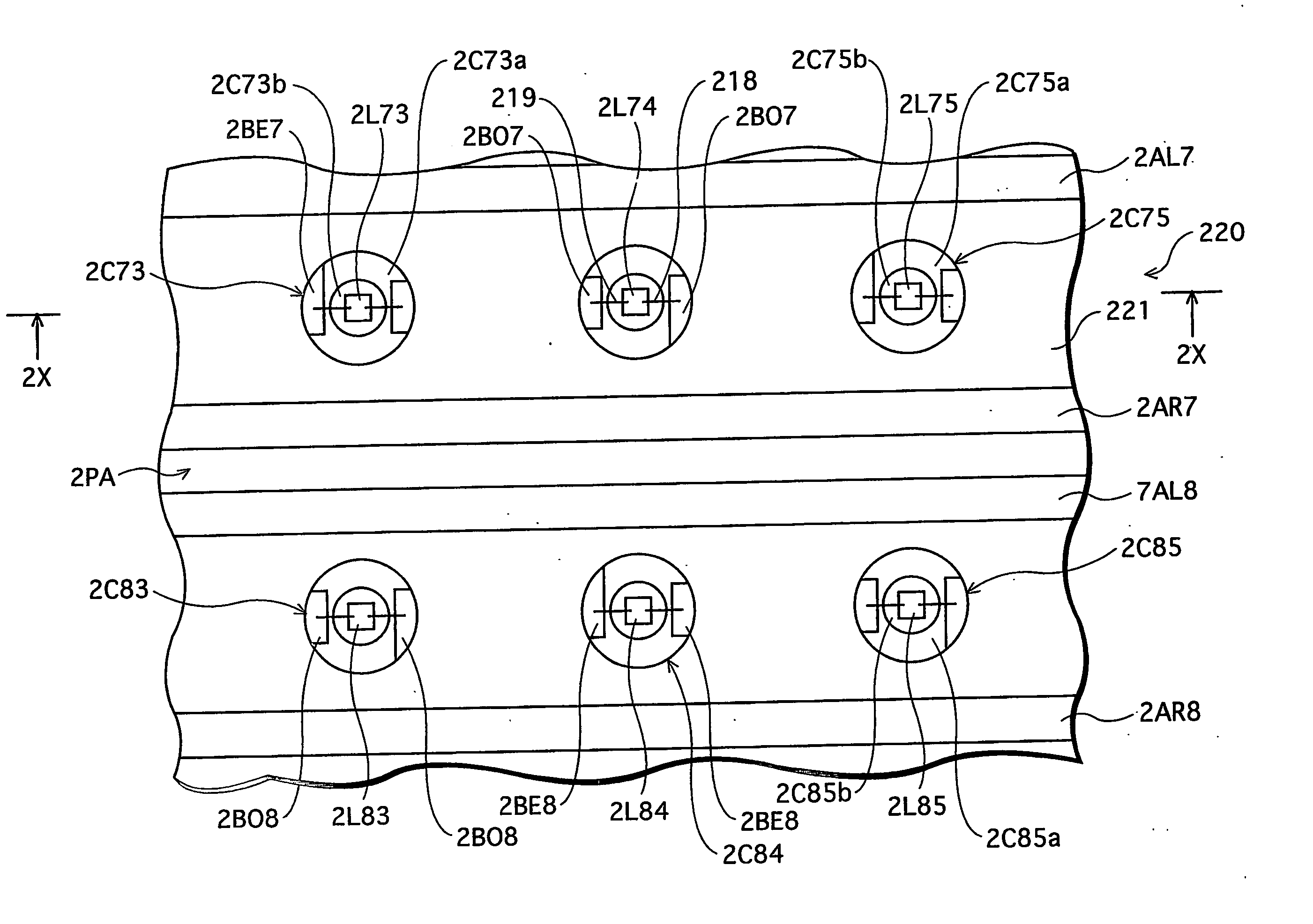
[0171] Embodiment 2 is different from Embodiment 1 in that the recesses formed in the metal base wiring board pass through the insulation substrate and reach the metal base.

1. Construction of LED Light Source

[0172] As is the case with Embodiment 1, an LED light source in Embodiment 2 includes a metal base wiring board and a plurality of LED bare chips which are mounted in the metal base wiring board. Also, recesses are formed in the front surface of the metal base wiring board in a matrix with 8 rows and 8 columns, and the LED bare chips are mounted on the bottom faces of the recesses, respectively.

[0173] In Embodiment 2, the recesses are denoted by 2Cnm, and the LED bare chips are denoted by 2Lnm.

[0174] In Embodiment 1, the bottom faces of the recesses Cnm are the front surface of the lower insulation layer 22 of the insulation substrate 20, while in Embodiment 2, the bottom faces of the recesses 2Cnm are the front surface of the metal base. That is to say, the recesses 2Cnm p...

embodiment 3

[0204] Embodiment 3 of the present invention is a metal base wiring board that has light emitting elements on the front surface of an insulation substrate, the insulation substrate containing heat conductive members between the light emitting elements and a metal base.

1. Construction of LED Light Source

[0205]FIG. 13 is a top plan view of a metal base wiring board 13 in Embodiment 3.

[0206] As is the case with Embodiments 1 and 2, the metal base wiring board 310 is composed of: an insulation substrate 320 composed of a plurality of insulation layers (two layers in the case of Embodiment 3, see FIG. 16) made of a material containing thermosetting resin and inorganic fillers, where wiring patterns made of copper (Cu) are formed on the front and rear surfaces of the insulation substrate 320; and a metal base 324 that is attached to a rear surface of the insulation substrate 320 (see FIG. 16).

[0207] As shown in FIG. 16, the insulation substrate 320 has an upper insulation layer 321 o...


PUM


Abstract

A metal base wiring board including: an insulation substrate composed of an upper insulation layer and a lower insulation layer; and a metal base attached to a rear surface of the insulation substrate. In front surfaces of the upper and lower insulation layers, wiring patterns are embedded and connected to each other. The insulation substrate has a plurality of recesses whose bottom faces are exposed areas of the front surface of the lower insulation layer. LED bare chips are mounted on the bottom faces of the recesses so as to be connected to the wiring pattern of the lower insulation layer.

Description

TECHNICAL FIELD [0001] The present invention relates to a metal base wiring board for retaining light emitting elements, a light emitting source composed of the metal base wiring board and the light emitting elements mounted therein, and a lighting apparatus and a display apparatus using the light emitting source, specifically to a technology for improving heat dissipation during light emission by the light emitting elements. BACKGROUND ART [0002] An LED light source using LED (Light Emitting Diode) is required to retain a lot of LEDs on a surface thereof (that is, on a surface of an insulation layer) since each LED outputs a small amount of optical power. The LEDs generate heat as they emit light, and increase the temperature thereof. The increase in temperature leads to reduction of light emitting efficiency or short life of LEDs. [0003] One of technologies proposed to improve the heat dissipation of such light emitting sources is a metal base wiring board in which a metal base is...

Claims


Application Information

Patent Timeline
IPC IPC(8): H01L33/00F21V29/00F21Y103/37H01L25/075H01L33/62H01L33/64H05K1/02H05K1/05H05K1/18
CPCF21Y2101/02F21K9/137H01L25/0753H01L33/641H05K1/0203H05K1/183H01L2224/45144H01L2224/48091H01L2224/73265F21Y2105/001H01L2924/00014H01L2924/00F21Y2105/10F21K9/233F21Y2115/10H05K1/021
Inventor MATSUI, NOBUYUKISETOMOTO, TATSUMITAMURA, TETSUSHISHIMIZU, MASANORIYAMASHITA, YOSHIHISA
Owner PANASONIC CORP
Why Eureka
Try Eureka