Stacked packaging methods and structures

a technology of stacked packaging and packaging methods, applied in the direction of semiconductor devices, electrical equipment, semiconductor/solid-state device details, etc., can solve the problems of csp b warpage and destruction of stacked structures

Inactive Publication Date: 2006-03-02
TAIWAN SEMICON MFG CO LTD
View PDF3 Cites 83 Cited by
  • Summary
  • Abstract
  • Description
  • Claims
  • Application Information

AI Technical Summary

Problems solved by technology

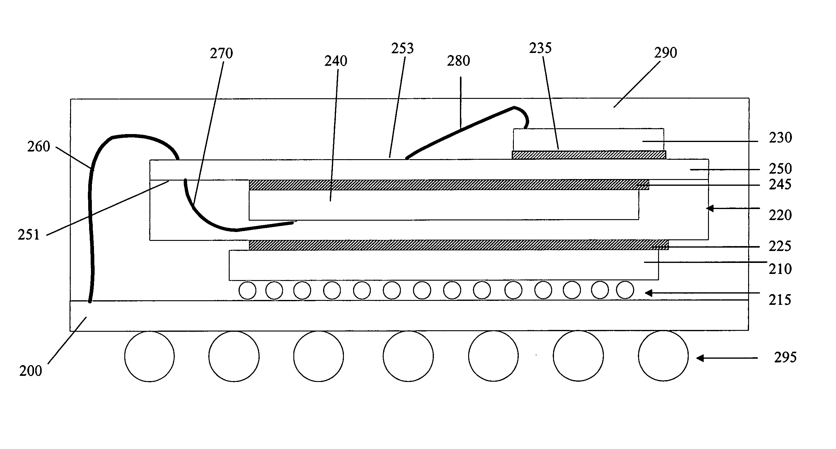
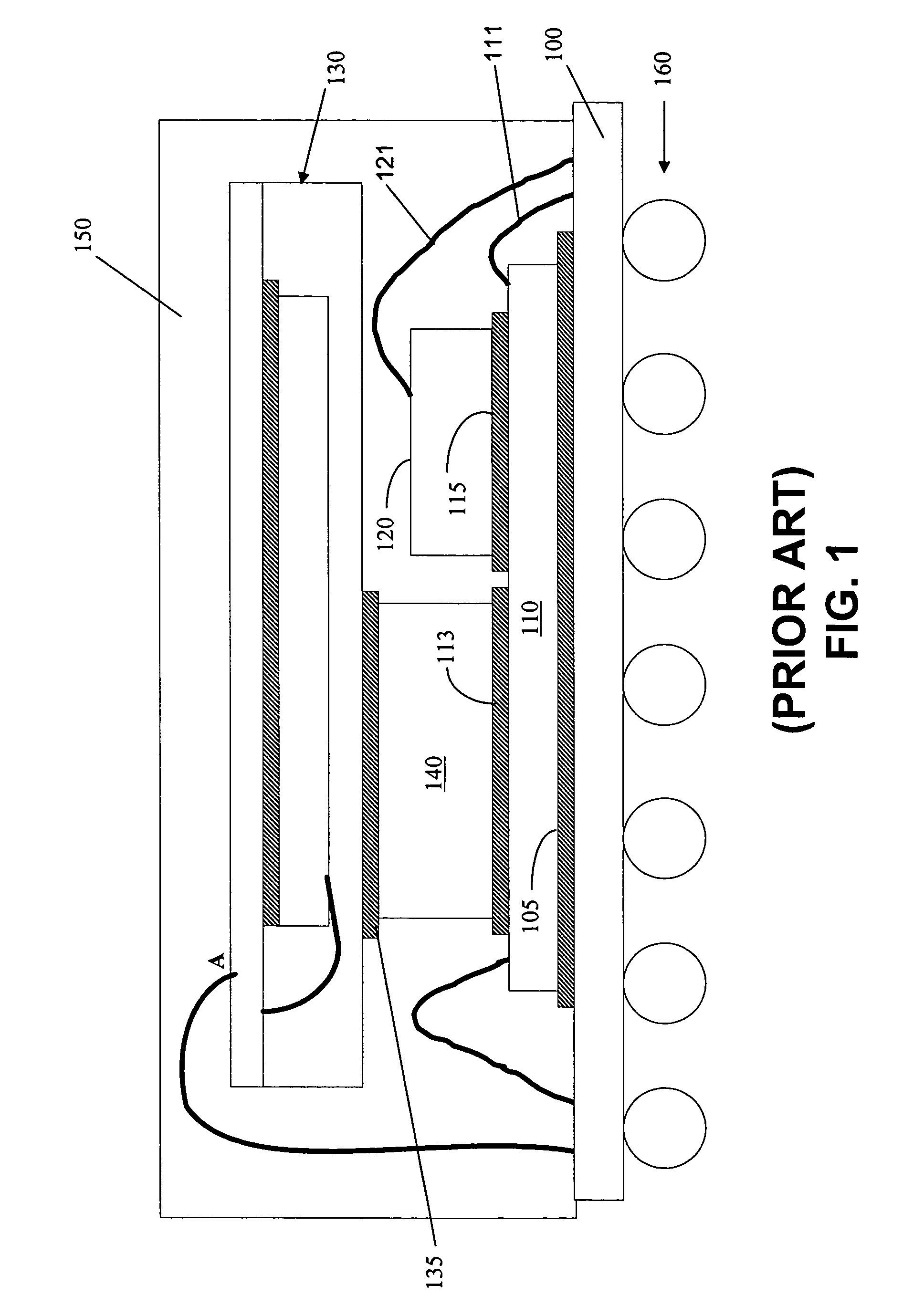
This can lead to warpage of the CSP 130.
The mechanical force may flip the CSP 130 and result in destruction of the stacked structure.

Method used


Image

  • Stacked packaging methods and structures
  • Stacked packaging methods and structures
  • Stacked packaging methods and structures

Examples


Embodiment Construction

[0018] This description of the exemplary embodiments is intended to be read in connection with the accompanying drawings, which are to be considered part of the entire written description. In the description, relative terms such as “lower,”“upper,”“horizontal,”“vertical,”, “above,”“below,”“up,”“down,”“top” and “bottom” as well as derivative thereof (e.g., “horizontally,”“downwardly,”“upwardly,” etc.) should be construed to refer to the orientation as then described or as shown in the drawing under discussion. These relative terms are for convenience of description and do not require that the apparatus be constructed or operated in a particular orientation. Terms concerning attachments, coupling and the like, such as “connected” and “interconnected,” refer to a relationship wherein structures are secured or attached to one another either directly or indirectly through intervening structures, as well as both movable or rigid attachments or relationships, unless expressly described oth...


PUM


Abstract

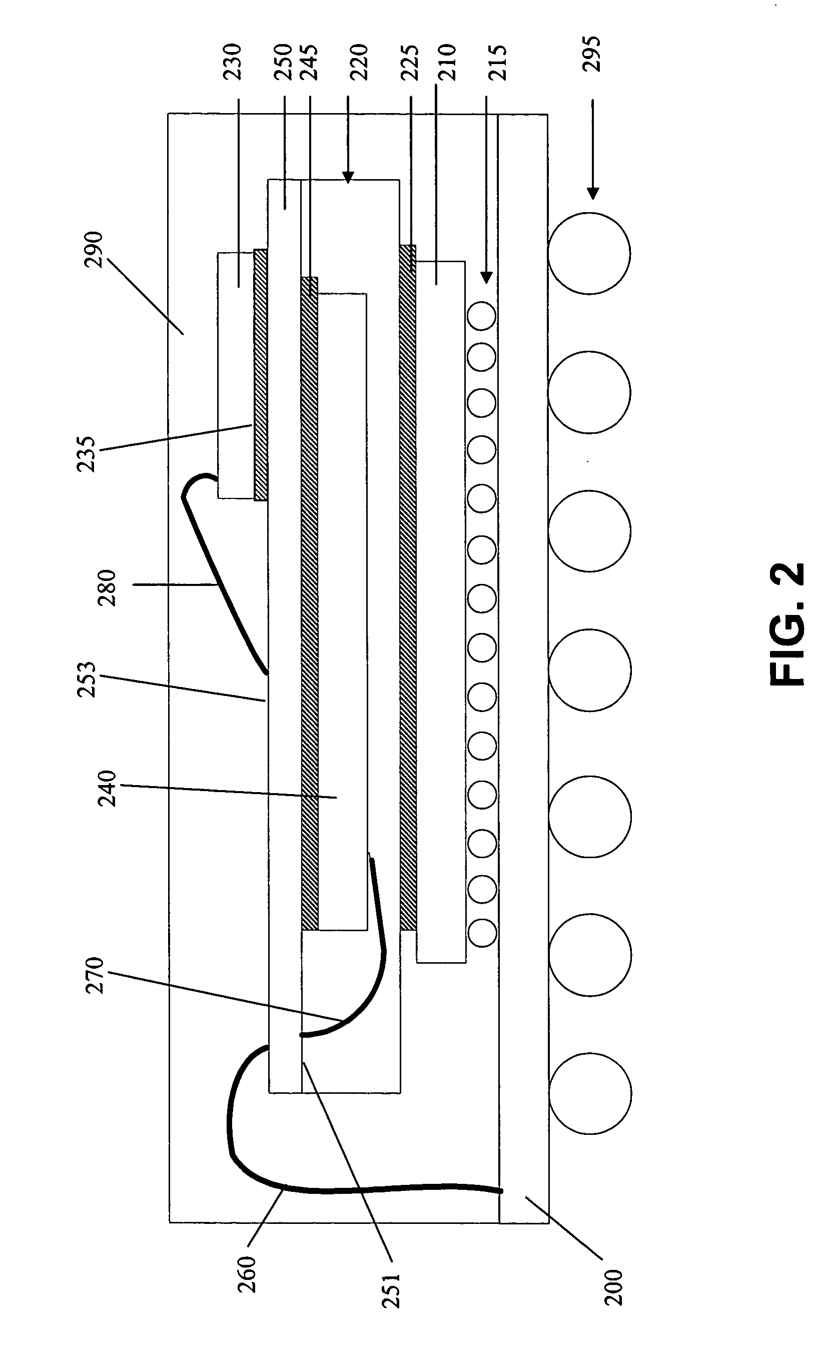
A packaging method and structures are disclosed. A first die is mounted on a package substrate. A chip scale package is mounted on the first die. The chip scale package comprises a chip scale package substrate and a second die mounted on a first surface of the chip scale package substrate. A third die is mounted on a second surface of the chip scale package substrate. Accordingly, the height of the stacked package can be reduced.

Description

FIELD OF THE INVENTION [0001] The present invention relates to packaging methods and structures and, more particularly relates to stacked packaging methods and structures. BACKGROUND OF THE INVENTION [0002] The need for increased memory capacity with a smaller footprint has led to development of stacked packages and packaging techniques. Stacked packages generally allow smaller, thinner packages. For many years, new package form factors have allowed size reduction in both the length and width (X and Y dimensions) of packages. More recently, there has been an increased interest in reducing the height (Z dimension). Increased use of portable devices, such as the exponential grown in wireless communications has increased the need for even more dramatic height (Z dimension) reduction. To meet these challenges, stacked packaging has been achieved, typically by stacking two or more die within a single package. [0003] Stacked packages allow more semiconductor functions per unit of area of ...

Claims


Application Information

Patent Timeline
Patent Type & Authority Applications(United States)
IPC IPC(8): H01L23/02
CPCH01L25/03H01L2224/16225H01L2224/48091H01L2224/48227H01L2224/73265H01L2924/01079H01L2924/15311H01L2924/3025H01L2224/32225H01L2924/19107H01L2224/73253H01L2224/45144H01L2924/00014H01L2924/00H01L2924/00012H01L24/73H01L2924/14H01L2924/00011H01L2224/0401
Inventor SU, CHAO-YUANTSAO, PEI-HAWHUANG, CHENDER
Owner TAIWAN SEMICON MFG CO LTD
Why Eureka
Try Eureka