
Charger

a technology of chargers and charging bodies, applied in the field of chargers, can solve the problems of inability to accurately detect the temperature of batteries in the structure, the structure cannot provide accurate detection of battery temperature, and the difficulty of a charger of these types of structures to accurately detect the temperature of batteries, etc., and achieve the effect of simple structur

Inactive Publication Date: 2006-03-02
SANYO ELECTRIC CO LTD
View PDF10 Cites 15 Cited by
  • Summary
  • Abstract
  • Description
  • Claims
  • Application Information

AI Technical Summary

Benefits of technology

[0014] Therefore, the present invention has been developed for solving the disadvantages. It is an important object to provide a charger capable of charging a battery in ideal temperature conditions while detecting its battery temperature in high accuracy with small time delay by a temperature sensor.
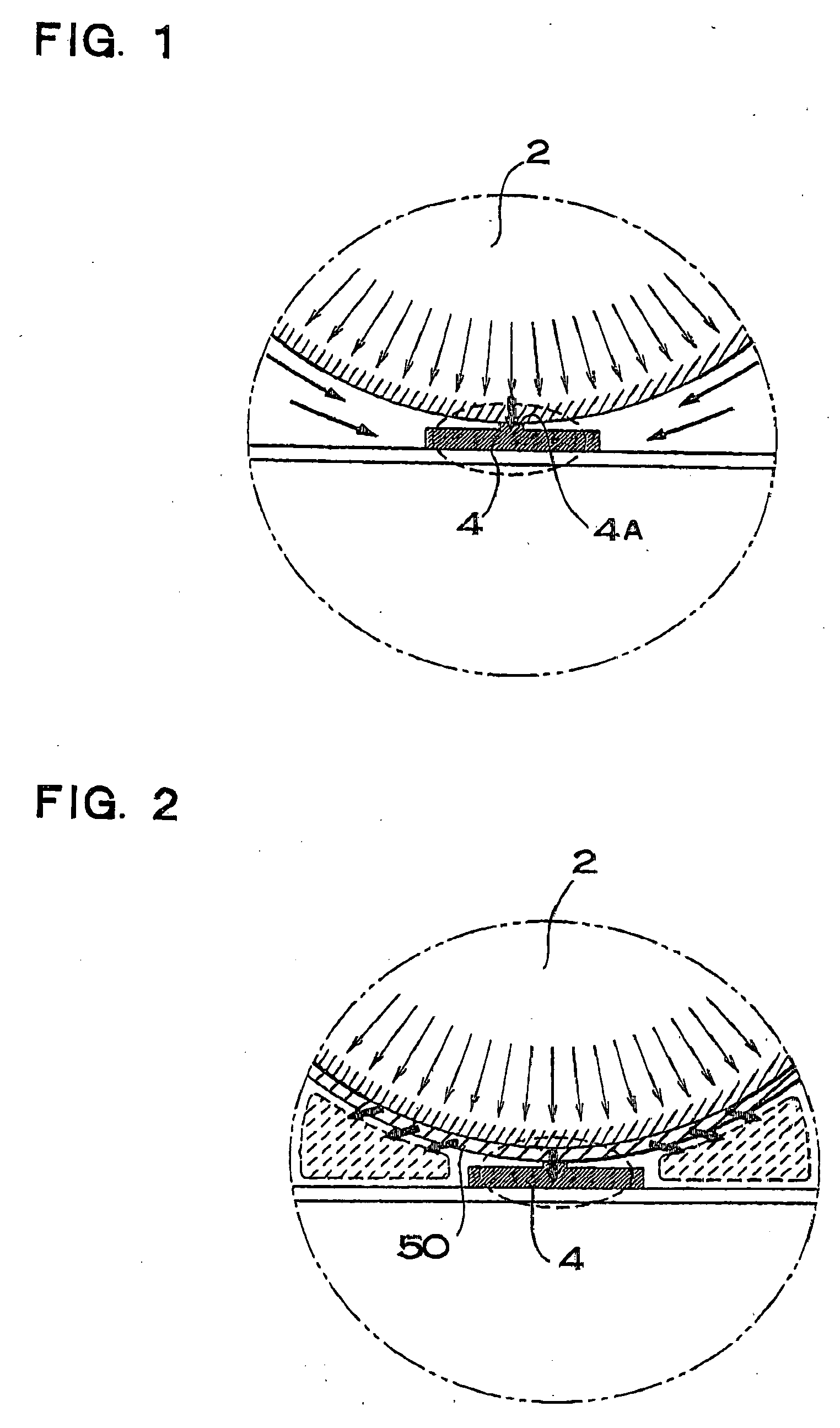
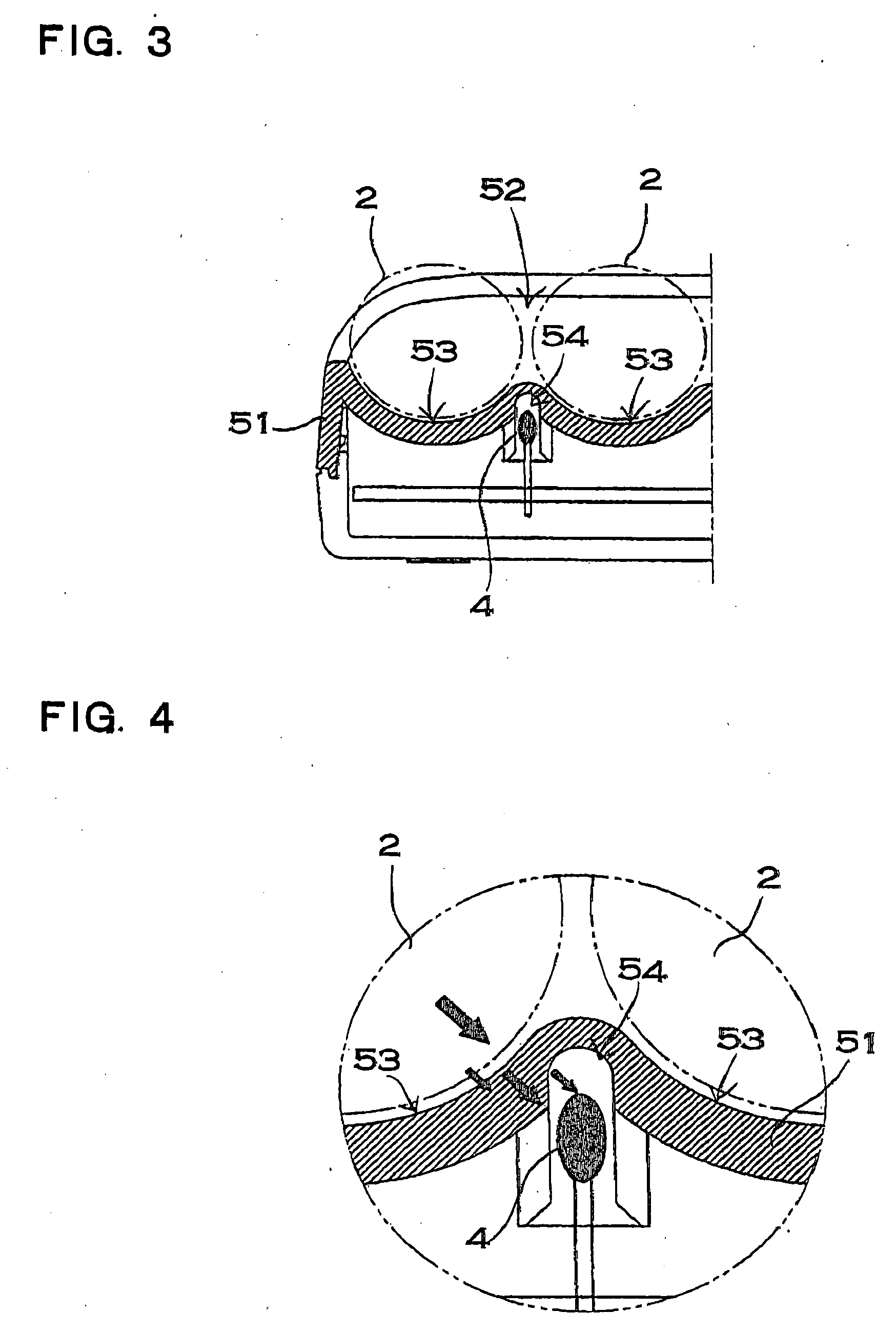
[0016] The aforementioned charger has a feature that can charge a battery in ideal temperature conditions while detecting its battery temperature in high accuracy with small time delay by a temperature sensor. The reason is that, in the charger according to the present invention, the temperature detection portion that comes in contact with the battery mounted to the battery pocket and detects its battery temperature includes the heat conduction plate and the temperature sensor, and the heat conduction plate has a characteristic structure that fastens the temperature sensor to the heat conduction plate. The heat conduction plate includes the pair of upper and lower sandwich plates that sandwich the temperature sensor, and the elastic connection arm connects first ends of the upper and lower sandwich plates, and the interlock portion couples second ends of the upper and lower sandwich plates, thus, the upper and lower sandwich plates sandwich and fasten the temperature sensor. Since, in the temperature detection portion of this structure, the sandwich plates sandwich and fasten the temperature sensor, heat generated in the battery can be conveyed from the heat conduction plate to the temperature sensor. Accordingly, it is possible to accurately and quickly detect the battery temperature. Consequently, the charger according the present invention can control battery charge in an ideal manner while detecting the temperature of the battery mounted to the battery pocket in high accuracy with small time delay by the temperature sensor.
[0018] In the charger including the heat conduction plate of the temperature detection portion that is the elastically deformable metal plate and has the elastic leg that elastically presses the sandwich plates toward the battery surface as mentioned above, an elastic force of the elastic leg can press the sandwich plate to bring it in firm contact with the battery surface. The temperature detection portion that allows the sandwich plate to come in firm contact with the battery surface has a feature that can more accurately detect the battery temperature. Particularly, in the charger including one of the sandwich plates having the pair of elastic legs that are connected to its both sides, the sandwich plate can be pressed in a good balance, thus, it is possible to bring the sandwich plate in contact with the batter surface in an ideal manner.
[0020] This charger has a very simple structure but can elastically press the sandwich plate toward the battery surface with elasticity of the elastic legs.

Problems solved by technology

It is difficult for a charger of these types of structures to accurately detect a battery temperature.
For this reason, even this structure cannot provide accurate detection of battery temperature.
As mentioned above, the battery temperature cannot be accurately detected in the structure where the temperature sensor is in direct contact with the battery nor the structure where the temperature sensor is in thermal contact with the battery through the metal plate.
In addition, it is more difficult to accurately detect the battery temperature in real time without time delay.
However, the microcomputer cannot provide highly accurate correction for a sharp temperature rise in the end of charge nor environmental temperature variation due to repeated charging.
The reason is that behaviors of temperature sensor and battery temperature curve are not same, thus, the temperature sensor cannot respond to sharp variation of battery temperature.
As a result, it is more difficult to accurately detect the battery temperature.
In addition, when the battery temperature rises, it takes long time until the sensor temperature reaches the same temperature as the battery.
Accordingly, a defect that a battery temperature cannot be accurately detected without time delay cannot be solved.

Method used


Image

  • Charger
  • Charger
  • Charger

Examples


Embodiment Construction

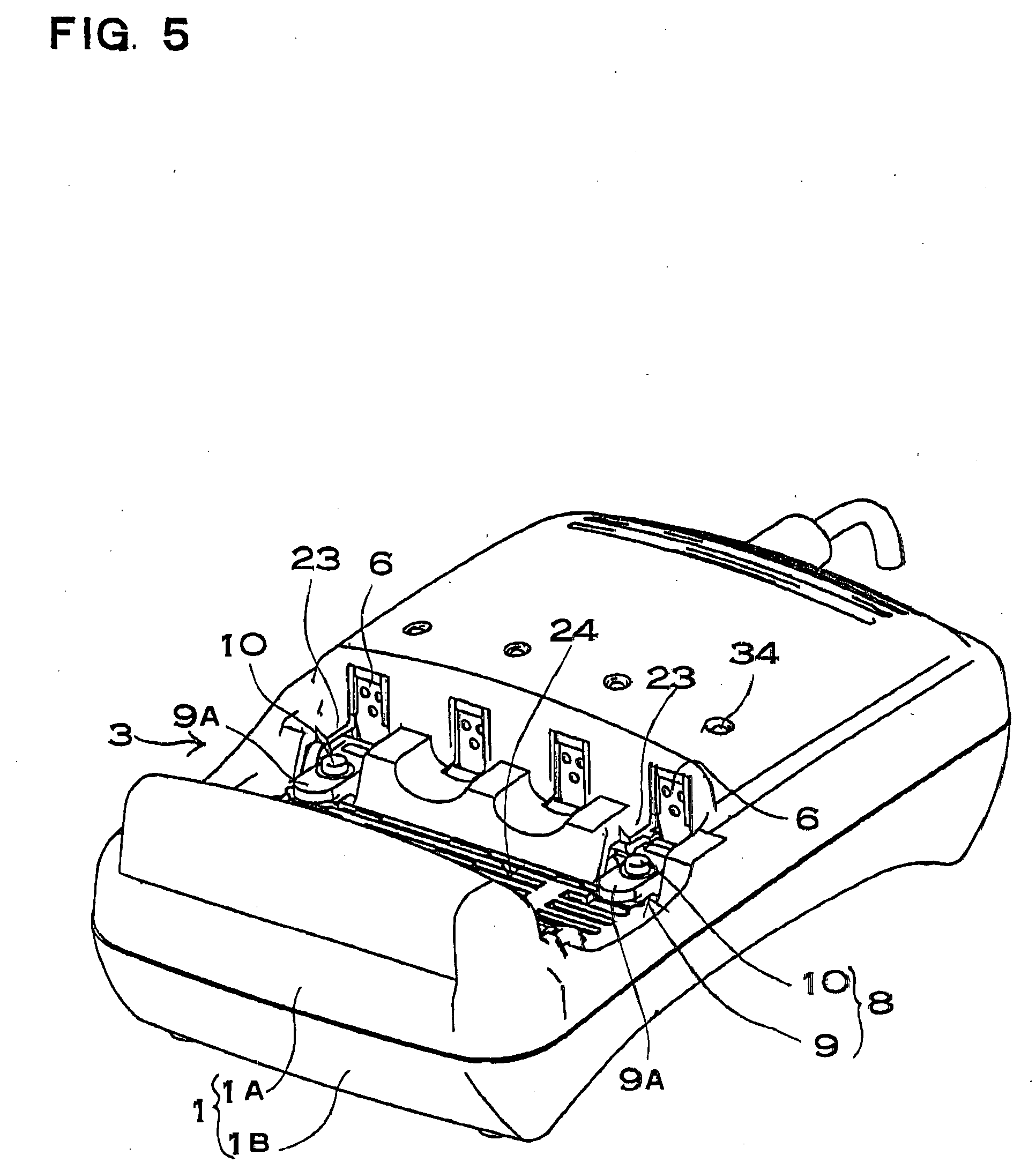
[0051] Hereinafter, first, an entire structure of a charger is described, then a heat conduction plate as a characteristic of the present invention is described in detail.

[0052] The charger shown in FIGS. 5 through 12 has an exterior rectangular box shape and is provided with a battery pocket 3 in an upper surface of a case 1 that detachably mounts a battery 2 to be charged. The case 1 shown in a plan view of FIG. 6 is provided with the battery pocket 3 in the lower part in this figure. The battery pocket 3 is provided with a temperature detection portion 12 that detects a temperature of the battery 2 mounted thereto. A charge circuit (not shown) that detects a battery temperature by the temperature detection portion 12 and controls an average charge current for the battery 2 is installed on a circuit board 5 in the case 1 of the charger. This charger is basically symmetric on the left and right sides except a power line 32, a socket 33, or the like, in the paper plane of FIG. 6.

[...


PUM


Abstract

A charger comprises a temperature detection portion that comes in contact with a battery detachably mounted to a battery pocket and detects its battery temperature, and a charge circuit that controls charge of the battery based on the battery temperature detected by the temperature detection portion. The temperature detection portion includes a heat conduction plate and a temperature sensor. The heat conduction plate includes a pair of upper and lower sandwich plates that sandwich the temperature sensor, and an elastic connection arm that connects the upper and lower sandwich plates at a first end side, and an interlock portion that couples the upper and lower sandwich plates at a second end side opposite to the first end side. The elastic connection arm connects first ends of the upper and lower sandwich plates, and the interlock portion couples second ends of the upper and lower sandwich plates, thus, the upper and lower sandwich plates sandwich and fasten the temperature sensor.

Description

BACKGROUND OF THE INVENTION [0001] 1. Field of the Invention [0002] The present invention relates to a charger that charges a battery to be charged while detecting a temperature of the battery. [0003] 2. Description of the Related Art [0004] When a battery is charged, its temperature rises. Particularly, when the battery is close to full charge, its temperature sharply rises. A rise of battery temperature causes deterioration of battery characteristics. In order to prevent deterioration of battery performance, a charger that has a temperature sensor for detecting a battery temperature has been developed (see Japanese Patent Laid-Open Publication TOKUKAI No. 2002-199609 and Japanese Patent Laid-Open Publication TOKUKAI No. HEI 5-30669). [0005] In the charger disclosed in Japanese Patent Laid-Open Publication TOKUKAI No. 2002-199609, a temperature sensor that is inserted in a soft tube is in contact with a surface of a battery pack. The temperature sensor is in thermal contact with th...

Claims


Application Information

Patent Timeline
Patent Type & Authority Applications(United States)
IPC IPC(8): H02J7/00
CPCH02J7/0091H02J7/0042H02J7/007194G01K13/20
Inventor NAKASHO, TOSHIKISATSUMA, EIJI
Owner SANYO ELECTRIC CO LTD
Learn More