Packet switching system, packet switching network and packet switching method

a packet switching and packet switching technology, applied in data switching networks, digital transmission, time-division multiplexing selection, etc., can solve the problems of resource allocation becoming a bottleneck, no significant improvement in performance, and limited throughput, and achieve small delays in cut-through and limited constraints.

Inactive Publication Date: 2008-12-09
HITACHI LTD
View PDF18 Cites 32 Cited by
  • Summary
  • Abstract
  • Description
  • Claims
  • Application Information

AI Technical Summary

Benefits of technology

[0012]It is therefore an object of the present invention to provide a large-capacity packet switching system which has only small delays in cut-through and has limited constraints on the number of flows that can be handled by the cut-through action.

Problems solved by technology

Therefore, where large quantities of packets need to be processed, the resource allocation becomes a bottleneck.
(1) Throughput is limited.
(2) The input interface of each ATM switch needs to have connection information set for each flow under size constraints of the table permitted for the input interface, only a limited number of flows is handled by cut-through operations.
(3) Delays in the dedicated VC resource allocation prevent the cut-through from providing any appreciable improvement in performance for packet transfers of short holding times. (4) Where packets are transferred through a plurality of packet switching systems connected in a multi-stage structure, no significant improvement in performance is attained if none of the switching systems performs a cut-through.
However, since the direct channel is not set in each switching system without a setting time, there is still the problem to be solved that there is little effect of lessening a total switching delay in the entire switching network.

Method used


Image

  • Packet switching system, packet switching network and packet switching method
  • Packet switching system, packet switching network and packet switching method
  • Packet switching system, packet switching network and packet switching method

Examples


Embodiment Construction

[0052]Preferred embodiments of this invention will now be described with reference to the accompanying drawings.

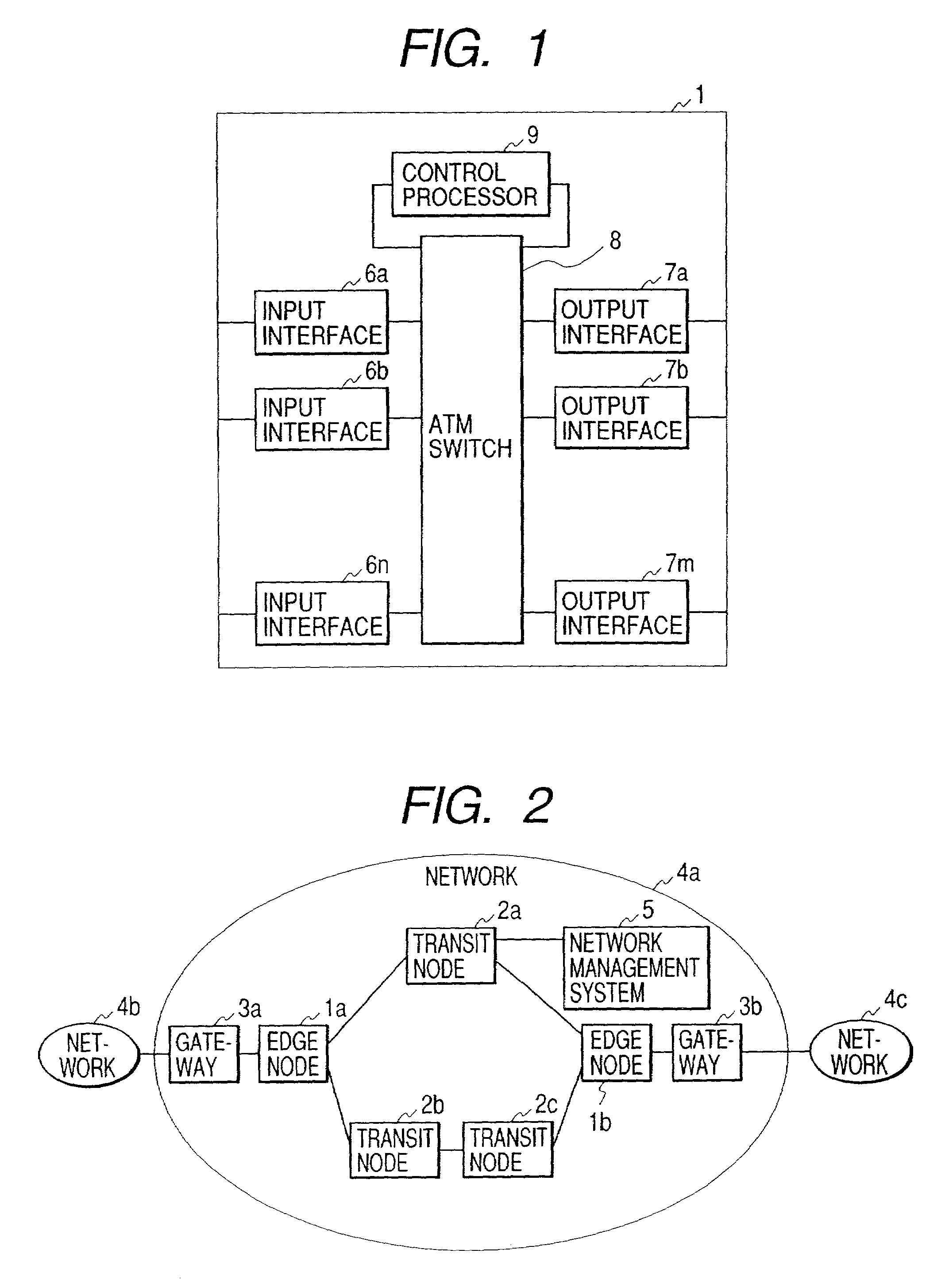
[0053]FIG. 2 shows a typical network constitution to which the invention is applied. In FIG. 2, reference numerals 1a and 1b stand for edge nodes; 2a, 2b and 2c for transit nodes; 3a and 3b for gateways; 4a, 4b and 4c for networks; and 5 for a network management system.

[0054]FIG. 1 depicts a typical constitution of the edge node 1 (1a, 1b). In FIG. 1 reference numeral 6 (6a, 6b, . . . , 6n) stands for an input interface, 7 (7a, 7b, . . . 7m) for an output interface, 8 for an ATM switch, and 9 for a control processor.

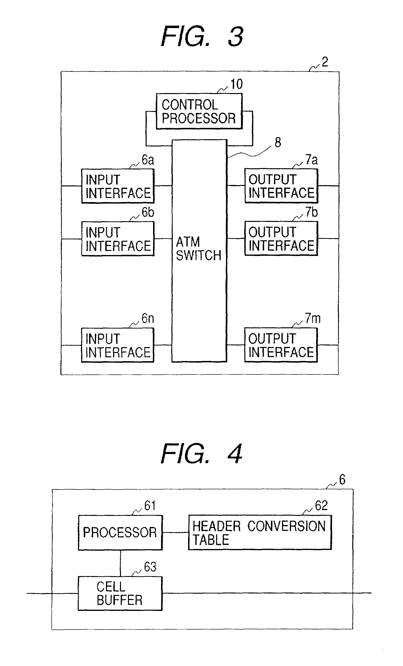
[0055]FIG. 3 illustrates a typical constitution of the transit node 2 (2a, 2b, 2c). In FIG. 3, reference numeral 6 (6a, 6b, . . . , 6n) stands for an input interface, 7 (7a, 7b, . . . , 7m) for an output interface, 8 for an ATM switch, and for a control processor.

[0056]FIG. 4 shows a typical constitution of the input interface 6 (6a, 6b, . . . , 6n). In FIG. 4,...


PUM


Abstract

Upon initialization, a VPC is set up between edge nodes. A control processor of each node creates an IP address/VPC mapping table using IP routing information and an address mapping table mapping correspondence between IP addresses and ATM addresses and supplied by a network management system. A gateway assigns a VCC to each packet input to the network. A sending-side edge node inputs the packet to the VPC corresponding to its destination by referring to the IP address/VPC mapping table. A transit node performs packet switching over VP. A receiving-side edge node transfers each packet to the gateway corresponding to its destination. If a series of packets meet a predetermined condition in a given edge node, its control processor sends VCC information to input interfaces of the edge node so that the packets are switched by an ATM switch in the edge node without intervention of the control processor.

Description

[0001]The present application is a continuation of U.S. application Ser. No. 09 / 079,150 filed May 15, 1998, now U.S. Pat. No. 6,275,494.BACKGROUND OF THE INVENTION[0002]The present invention relates to a packet switching system and, more particularly, to a packet switching system which, in sending and receiving packets over ATM (Asynchronous Transfer Mode) lines, switches the packets based on the IP (Internet Protocol) routing protocol.[0003]Recent years have seen a surge in traffic of packet communications based on the IP thanks in part to the introduction of novel applications such as the WWW (World Wide Web). IP packet switching was carried out conventionally on a packet-by-packet basis with reference to a routing table prepared according to the IP routing protocol. The switching was conducted primarily by software, and it was desired to increase the speed of the processing in the face of an ever-swelling volume of traffic.[0004]One way to address the need for high-speed processi...

Claims


Application Information

Patent Timeline
Patent Type & Authority Patents(United States)
IPC IPC(8): H04L12/28H04L45/50H04Q3/00H04L47/43H04Q11/04
CPCH04L49/251H04L49/254H04L49/3009H04L49/3081H04L49/602H04L49/606H04Q11/0478H04L49/30H04L2012/5667
Inventor ENDO, NOBORUTAKASE, AKIHIKOABE, HAJIMEMIKI, KAZUHO
Owner HITACHI LTD
Why Eureka
Try Eureka