Information recording medium, and method and apparatus for managing defect thereof

a technology of information recording medium and defect management, which is applied in the direction of recording signal processing, digital signal error detection/correction, instruments, etc., can solve the problems of inability to manage user data recorded in the optical disk, inability to use slipping replacement algorithm, and inability to assign all lsns after one defective sector, etc., to keep the delay in access relatively small

Inactive Publication Date: 2004-05-25
PANASONIC CORP
View PDF38 Cites 37 Cited by
  • Summary
  • Abstract
  • Description
  • Claims
  • Application Information

AI Technical Summary

Benefits of technology

Thus, the invention described herein makes possible the advantages of providing (1) an information recording medium and a method and an apparatus for managing a defect thereof for keeping a delay in access relatively small even when a defective sector is detected in a file management area located in the vicinity of a sector to which LSN:0 is assigned; and (2) an information recording medium, and a method and an apparatus for managing a defect thereof for allowing the location of an LR spare area to be found with substantially no calculation.

Problems solved by technology

A disadvantage of the slipping replacement algorithm is that the assignment of all the LSNs is slipped after one defective sector.
When the assignment of the LSNs to the sectors is slipped, the host computer cannot manage user data recorded in the optical disk.
Accordingly, the slipping replacement algorithm is not usable after the user data is recorded in the optical disk.
A disadvantage of the linear replacement algorithm is that a delay in access caused by a defective sector is relatively large.
As shown in FIG. 27, the conventional linear replacement algorithm has a problem in that, when a sector having a small physical sector number is defected as a defective sector, a delay in access caused by the defective sector is relatively large since the distance between the defective sector and the replacing sector is relatively long.
Since the file management area 10 located in the vicinity of the sector to which LSN:0 is assigned is accessed each time a file is recorded, a defective sector in the file management area 10 may directly cause undesirable reduction in the access speed to the optical disk.

Method used


Image

  • Information recording medium, and method and apparatus for managing defect thereof
  • Information recording medium, and method and apparatus for managing defect thereof
  • Information recording medium, and method and apparatus for managing defect thereof

Examples


example 1

1. Structure of an Information Processing System

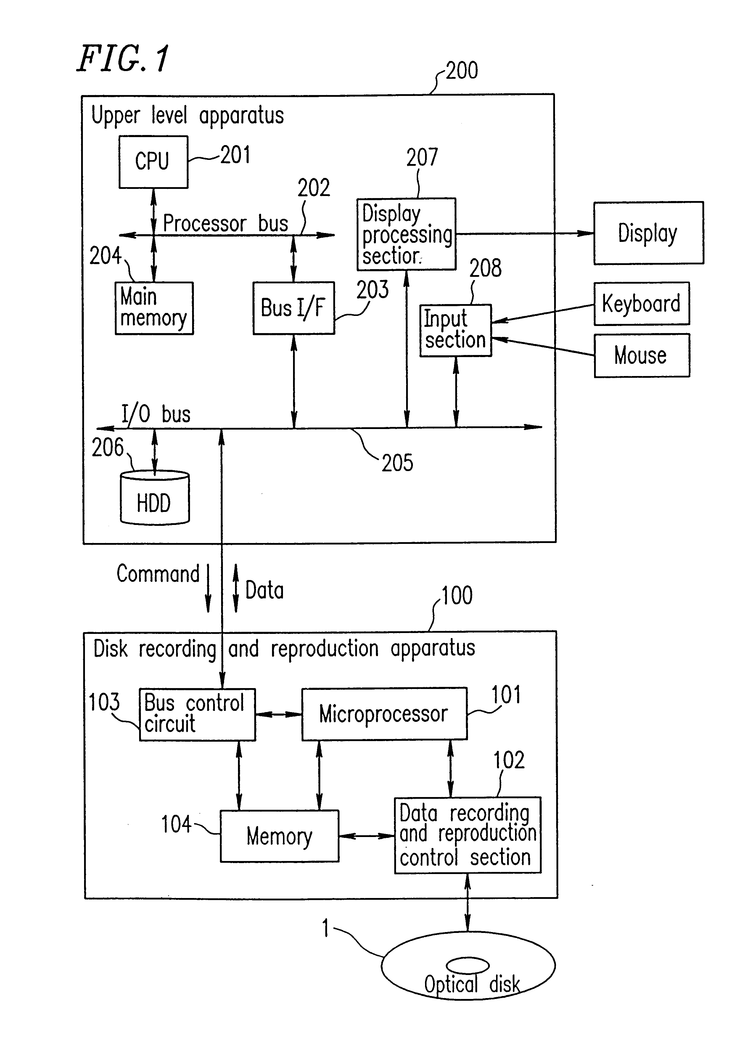
FIG. 1 shows a structure of an information processing system in a first example according to the present invention. The information processing system includes an upper level apparatus 200 and a disk recording and reproduction apparatus 100. The disk recording and reproduction apparatus 100 records information to a rewritable optical disk 1 or reproduces information recorded in the optical disk 1 in accordance with a command from the upper level apparatus 200. The upper level apparatus 200 is, for example, a personal computer.

The upper level apparatus 200 includes a CPU 201, a main memory 204, a bus interface (bus I / F) 203, a processor bus 202, an I / O bus 205, a hard disk device (HDD) 206, a display processing section 207, and an input section 208. The upper level apparatus 200 is connected to the disk recording and reproduction apparatus 100 through the I / O bus 205.

The processor bus 202 is a high speed bus through which the CPU 201 acc...

example 2

Methods for managing a defect of an optical disk which are preferable to AV files (Audio Visual Data Files; i.e., time-continuous video and audio data files), for which real-time recording and reproduction is important have been proposed in, for example, Goto et al., International Publication WO98 / 14938. According to such methods, when AV files are recorded in the optical disk 1, defect management is performed using a file system which is managed by the upper level apparatus 200 without performing replacement processing based on the linear replacement algorithm.

Hereinafter, an example of a method for managing a defect of an optical disk according to the present invention applied to an AV file system will be described.

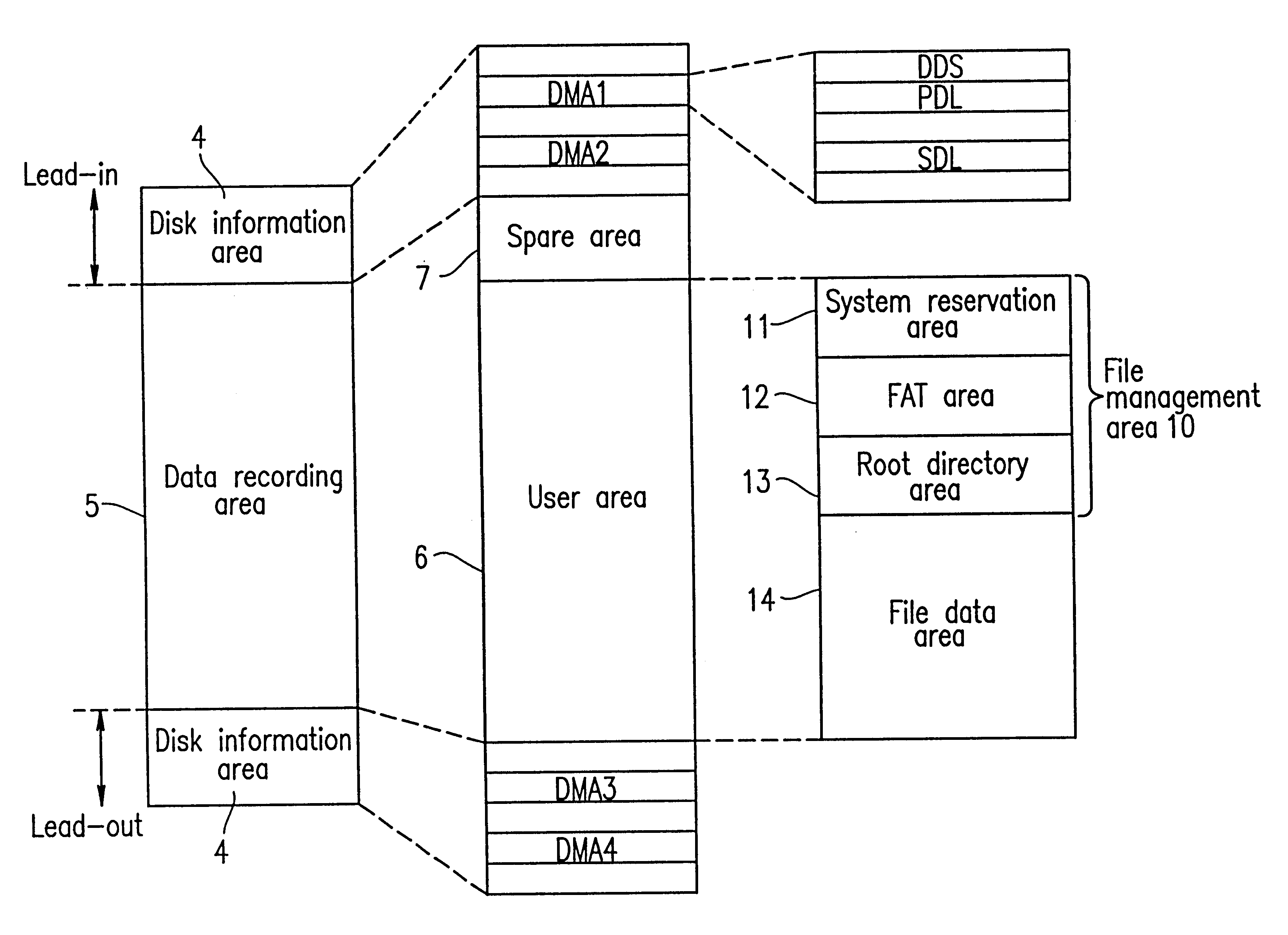
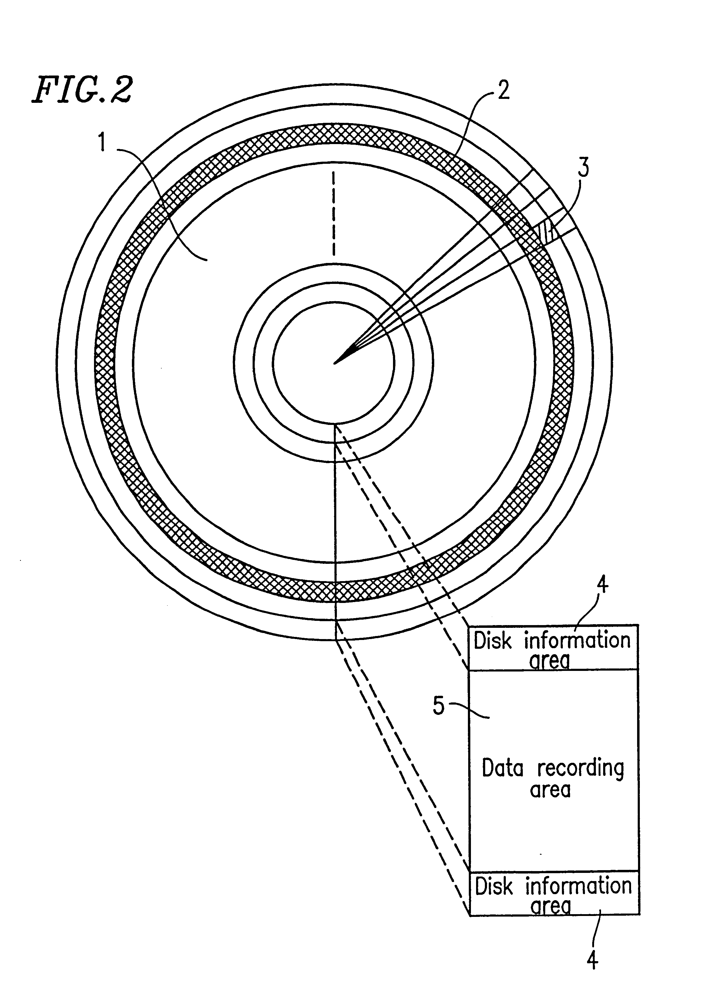
The information processing system has the structure shown in FIG. 1. The optical disk 1 has the physical structure shown in FIG. 2 and the logical structure shown in FIG. 3. The file system is different from the MS-DOS file system described in the first example, but is ...

example 3

A ZCLV system information recording medium, in which the combined spare area and user area is divided into a plurality of zones which have different disk rotation speeds, such as a DVD-RAM disk or the like, has a guard area on the border between adjacent zones.

FIG. 20 shows a physical structure of an optical disk 1a having two zones. The optical disk 1a has zone 0 in an inner part thereof and zone 1 located radially outward from zone 0. A guard area 2001 is provided on the border between zones 0 and 1 so as to cover a part of each zone. A part 2001a of the guard area 2001 in zone 0 and a part 2001b of the guard area 2001 in zone 1 each include at least one track.

The part 2001a and the part 2001b of the guard area 2001 have tracks of different structures. Accordingly, the signal quality in the guard area 2001 is inferior, and therefore the guard area 2001 is not suitable for recording. The guard area 2001 is set as an area in which no data is to be recorded. The locations and sizes o...


PUM

PropertyMeasurementUnit
areaaaaaaaaaaa
sector structureaaaaaaaaaa
densityaaaaaaaaaa

Abstract

An information recording medium includes a disk information area; a user area including a plurality of sectors; and a spare area including at least one sector which, when at least one of the plurality of sectors included in the user area is a defective sector, is usable instead of the at least one defective sector. The spare area is located radially inward from the user area. A physical sector number of a sector to which a logical sector number "0" is assigned, among the plurality of sectors included in the user area and the at least one sector included in the spare area, is recorded in the disk information area.

Description

BACKGROUND OF THE INVENTION1. Field of the InventionThe present invention relates to an information recording medium, and a method and an apparatus for managing a defect thereof.2. Description of the Related ArtA representative information recording medium having a sector structure is an optical disk. Recently, the density and capacity of optical disks have been improved. Therefore, it is important to guarantee the reliability of optical disks.FIG. 23 shows a logical structure of a conventional optical disk.As shown in FIG. 23, the optical disk includes two disk information areas 4 and a data recording area 5. The data recording area 5 includes a user area 6 and a spare area 8. The spare area 8 is located radially outward from the user area 6 on the optical disk.The user area 6 includes a system reservation area 11, a FAT (File Allocation Table) area 12, a root directory area 13, and a file data area 14. The system reservation area 11, the FAT area 12, and the root directory area 13...

Claims


Application Information

Patent Timeline
Patent Type & Authority Patents(United States)
IPC IPC(8): G11B20/18
CPCG11B20/18G11B20/1883G11B2220/20G11B2020/1893
Inventor SASAKI, SHINJIITO, MOTOSHIUEDAFUKUSHIMA, YOSHIHISA
Owner PANASONIC CORP
Why Eureka
Try Eureka