Robot arm control method and control device

a robot arm and control method technology, applied in the field of robot arm control methods and control devices, can solve the problems of inability to suppress the electric current command of the motor, inability to control the robot arm, and inability to meet the requirements of the robot arm,

Active Publication Date: 2006-09-05
PANASONIC CORP
View PDF25 Cites 33 Cited by
  • Summary
  • Abstract
  • Description
  • Claims
  • Application Information

AI Technical Summary

Benefits of technology

[0094]The present invention has been accomplished to solve the above problems. It is an object of the present invention to provide a control method, the compliance of which can be enhanced by suppressing the electric current restriction to be lower than the frictional torque by conducting feedback control in the compliance control of a robot driven by a motor.
[0095]It is another object of the present invention to provide a control method of controlling a robot capable of highly accurately detecting a collision torque by making a dynamic friction torque of a reduction gear coincide with not a fixed value but a value corresponding to the actual characteristic.
[0096]It is still another object of the present invention to provide a control method of controlling a robot capable of enhancing the motor torque calculating accuracy before operation and obtaining the most appropriate feedforward compensation, the delay of the phase of which is small, by making a dynamic friction torque of a reduction gear coincide with not a fixed value but a value corresponding to the actual characteristic.

Problems solved by technology

However, according to a stoppage means for stopping a robot arm by detecting an external force, which is given to the robot at the time of collision, with a force sensor, the manufacturing cost and the weight are undesirably increased.
Therefore, when the robot arm is operated only by feedback control, it is difficult to suppress an electric current command of the motor.
However, actually, an error of calculation is caused by the parameter error of the expression (3).
Therefore, when the electric current is intensely suppressed in feedback control, it becomes impossible to compensate the error, and the robot arm becomes out of control and the positional deviation can not be decreased, that is, there is a possibility that the robot arm runs away.
However, when the robot is actively operated from a state in which the robot is completely stopped, the operating direction is unknown until the robot starts operating.
Therefore, it is impossible to calculate the stationary friction torque τμs.
However, in the case where an angular velocity fluctuation is caused by the disturbance torque τdis in the middle of the operation, a big error is caused between the angular velocity command ωcom (13) and the actual angular velocity ωfb (reference numeral 23 in FIG. 3).
Further, even when the robot is not pushed by an external force, a delay of follow is caused in the feedback control conducted by the feedback controller in the actual operation.
That is, at the point of time when the angular velocity command ωcom (13) reaches 0, the robot is suddenly stopped and can not reach an objective position and further there is a possibility that vibration is caused.
In other words, although the frictional compensation is being conducted, it is impossible to set the feedback electric current command to be lower than the actual frictional torque.
Therefore, the robot compliance can not be enhanced.
Accordingly, although the compliance can be enhanced, the feedback system becomes vibrational.
However, when the dynamic friction torque item is calculated as a fixed value, in the case where the motor generation torque is high at the time of acceleration and deceleration, a big calculation error of about 10% of the motor generation torque is caused.
Accordingly, by the estimation of the estimation algorithm, a delay of the phase is generated and it is impossible to completely conduct the compensation.
However, when the calculation is conducted with the expression (11) while the dynamic frictional torque is set at a fixed value, in the case where the motor generation torque is high at the time of acceleration and deceleration, a big calculation error of about 10% of the motor generation torque is caused.
However, when dynamic frictional torque τμ is increased while it is kept as a constant value, as shown in FIG. 13, although the error (4) at the time of peak torque is decreased, however, the error (5) at the time of a constant velocity is increased.
On the other hand, in the case of feedforward control of torque necessary for the reduction gear output, when the dynamic frictional torque τμ is considered to a constant, the calculation error is increased, and there is a possibility that the feedforward compensation torque becomes insufficient.
When the estimation algorithm is used so as to prevent the generation of the calculation error, it is difficult to estimate the frictional torque, which is suddenly changed at the time of acceleration or deceleration, without causing a delay of the phase.
Accordingly, there is a possibility that the deterioration of the control performance can not be sufficiently prevented.
Therefore, the responding property is not so high at the time of stopping the collision, and the stopping time is extended and it is impossible to prevent the occurrence of damage caused by the collision.
However, it is inferior to the responding property (several kHz) of the electric current control.
However, in order to enhance the compliance, it is necessary to reduce a gain proportional to the velocity, which deteriorates the velocity responding property and extends the stopping time.
It is difficult to make the stopping time and the compliance compatible with each other.
When this impressing time is short, it is impossible to sufficiently reduce the velocity, and the damage caused by the collision is increased.
When this impressing time is long, a redundant motion is conducted in the reverse direction, and there is a possibility that the robot arm causes the collision again.
However, only when the motor is stopped, the problem of the distortion caused by the collision can not be solved.
Since the generation of the maximum reverse torque itself is a state in which the control is generating the maximum output in an open loop, in the case where the velocity is so low that the robot can not be damaged even when it collides with an object, there is a higher risk of impressing the reverse torque.
Therefore, compared with the case in which the collision detecting sensor is provided, the detection error is increased.
For the above reasons, in the case of an axis, the collision detecting torque of which is low, there is a possibility that the direction is mistakenly detected and the appropriate stopping means can not be selected.
However, since the colliding direction is unknown, it is better not to reduce the motor rotating speed in some cases, that is, different from the method described in Japanese Patent No. 2871993, the reverse torque should not be impressed until the motor is stopped.

Method used


Image

  • Robot arm control method and control device
  • Robot arm control method and control device
  • Robot arm control method and control device

Examples


first embodiment

[0130

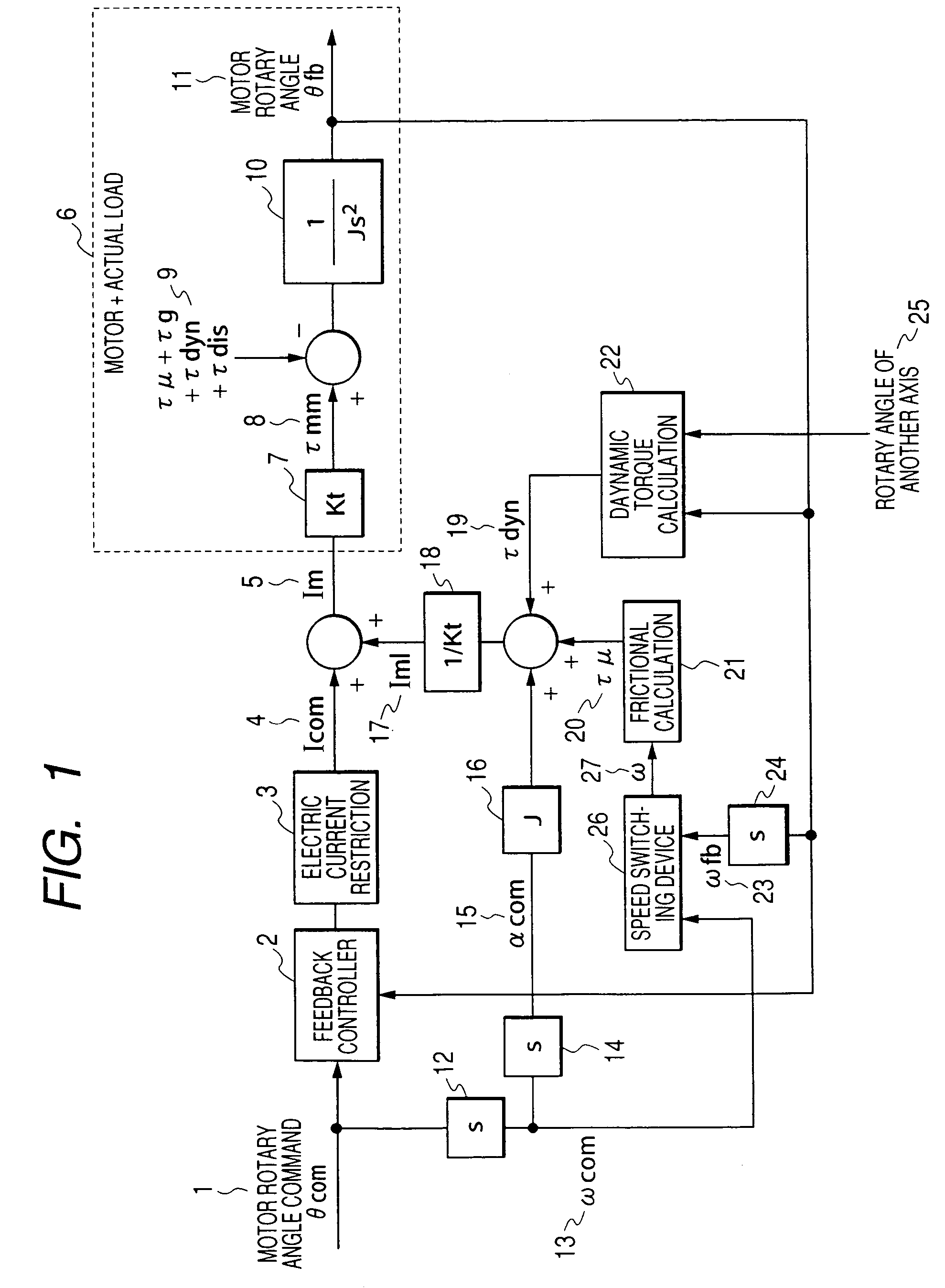
[0131]FIG. 1 is a block diagram showing the controlling method of the present invention. In FIG. 1, reference numeral 26 is a velocity switching device, and reference numeral 27 is an angular velocity ω selected by the velocity switching device. The feedback electric current command Icom (4) can be found in such a manner that PID calculation is conducted by the feedback controller (2) from the rotary angle command θcom (1) and the actual motor rotary angle θfb and that the electric current restriction (3) is conducted. Concerning the means for the electric current restriction (3), there are provided a system in which the limit is set and a system in which the feedback gain is lowered.

[0132]On the other hand, Iml (17) can be calculated by the expression (3) as follows. The angular acceleration αcom (15), which is found when the motor rotation command θcom (1) is subjected to the differential calculations (12), (14) twice, is multiplied by the motor inertia J (16). The frictional...

second embodiment

[0142

[0143]In the expression (12) showing a switch of velocity in the first embodiment, at least one of the velocity command value and the actually measured value is multiplied by a weighting factor.

[0144]ω={ω⁢⁢fb(kc1*ω⁢⁢com+kc2≤ω⁢⁢fb)ω⁢⁢com(kc1*ω⁢⁢com+kc2>ω⁢⁢fb)(13)

[0145]When the constitution is made as shown by the expression (13), priority is given to one of the velocity command value and the actually measured value so that it can be adopted as a velocity.

[0146]Since the actually measured value ωfb includes a measurement error, for example, when the weighting factor in the expression (13) is set at a value as follows, the velocity command ωcom can be preferentially selected.

kc1>1 and kc2>0  (14)

third embodiment

[0147

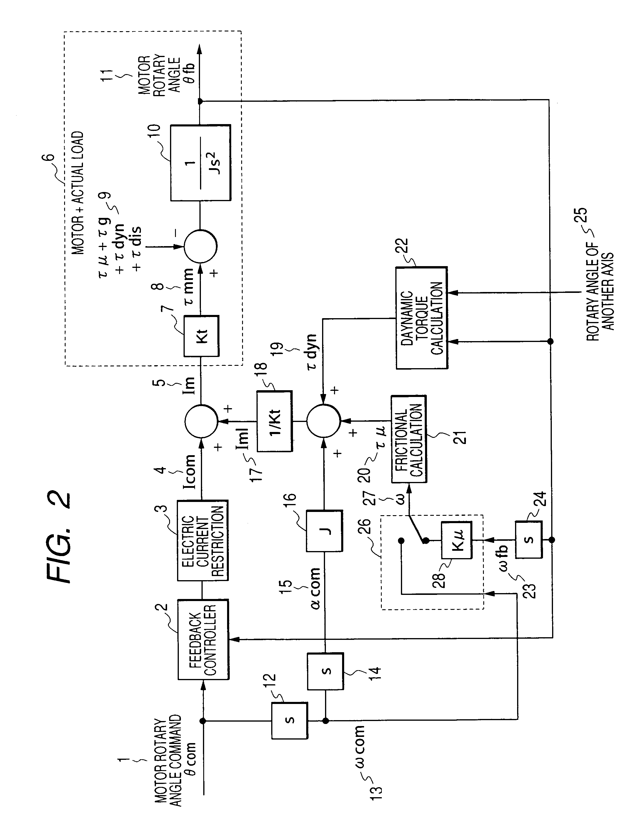
[0148]FIG. 2 is a block diagram showing a control method of the third embodiment.

[0149]The actual angular velocity ωfb (23) inputted into the velocity switching device (26) is multiplied by the frictional compensation rate kμ.

[0150]It is expressed by the expression (15) as follows.

[0151]ω={k⁢⁢μ*ω⁢⁢fb(kc1*ω⁢⁢com+kc2≤ω⁢⁢fb)ω⁢⁢com(kc1*ω⁢⁢com+kc2>ω⁢⁢fb)(15)

[0152]kμ: Frictional compensation rate

[0153]When the angular velocity ω (27) obtained by the above expression (15) is used, in the case where the actual angular velocity ωFB (23) is selected for the angular velocity used when the frictional torque τμ (20) is calculated (21) by the expression (5), when the frictional compensation rate kμ is set at a value not more than 1, the frictional torque τμ (20) can not be compensated by 100%. Therefore, it is possible to adjust so that the feedback characteristic can not be vibrational.

[0154]On the other hand, in the case where the angular velocity command ωcom (13) is used for the angul...


PUM


Abstract

When either a command value or an actually measured value is appropriately selected as an angular velocity used for the frictional torque calculation, the frictional compensation can be made valid at all times in both the case in which a robot is actively operated according to an angular velocity command and the case in which the robot is passively operated being pushed by an external force. In the case where a motor rotating direction and a collision direction are reverse to each other after a collision has been detected, the control mode is switched from the positional control to the electric current control and a torque, the direction of which is reverse to the direction of the motor rotation is generated by the motor, so that the motor rotating speed can be reduced and the collision energy can be alleviated. After that, when the motor rotating speed is reduced to a value not more than the setting value, the control mode is switched to the compliance control and the distortion caused in a reduction gear is dissolved. On the other hand, in the case where the motor rotating direction and the collision direction are the same, the control mode is directly switched from the positional control to the compliance control without passing through the electric current control. When the robot is operated whole following a collision force, the collision force can be alleviated.

Description

TECHNICAL FIELD[0001]The present invention relates to a method and device of controlling a robot arm driven by a motor. More particularly, the present invention relates to a technique of compliance servo control of controlling a robot arm, that is, the present invention relates to a method and device of controlling a stoppage of a robot arm conducted after a collision of the robot arm against an object has been detected.BACKGROUND ART[0002]Recently, robots have been used for not only the industrial field but also the public consumer field. Therefore, it has become important to ensure the safety. However, according to a stoppage means for stopping a robot arm by detecting an external force, which is given to the robot at the time of collision, with a force sensor, the manufacturing cost and the weight are undesirably increased. Accordingly, it is desired to enhance the performance of compliance servo control including the collision detection, in which no sensors are used, and the con...

Claims


Application Information

Patent Timeline
Patent Type & Authority Patents(United States)
IPC IPC(8): G05B6/02B25J13/00B25J9/16
CPCB25J9/1633B25J9/1676G05B19/4061G05B2219/42288G05B2219/39355G05B2219/40226
Inventor NAKATA, HIROYUKIMASUNAGA, NAOTOHASHIMOTO, ATSUMIMUKAI, YASUSHI
Owner PANASONIC CORP
Why Eureka
Try Eureka