Actuator

a technology of actuators and actuators, applied in the field of high-response actuators, can solve the problems of limited weight reduction of actuators comprising electromagnetic motors, slow response, and difficulty in forming alloys into springs, and achieve excellent response and large displacement and output.

Inactive Publication Date: 2006-03-02
HONDA MOTOR CO LTD
View PDF4 Cites 22 Cited by
  • Summary
  • Abstract
  • Description
  • Claims
  • Application Information

AI Technical Summary

Benefits of technology

[0009] Accordingly, an object of the present invention is to provide a precisely controllable actuator capable of providing large displacement and output with excellent response in a small magnetic field.

Problems solved by technology

However, because the output densities of the electromagnetic motors depend on their weight, only limited weight reduction is available in actuators comprising the electromagnetic motors.
However, the conventional actuators comprising shape memory alloy springs, which have a mechanism of deforming the springs by temperature change utilizing the thermoelastic martensitic phase transformation of the shape memory alloys, suffer from slow response because thermal diffusion determines the rate of deformation, though the actuators provide large output and displacement.
However it is difficult to form this alloy into springs because of brittleness.
Though this shape memory alloy exhibits excellent response because of magnetic control, it disadvantageously needs a larger magnetic field.
Though this magnetic-drive stage can achieve high-accuracy positioning, it provides only small displacement because of using the parallel spring.
This driving apparatus fails to achieve high-accuracy position control, despite positioning by the lock mechanism and the spring.

Method used


Image

  • Actuator
  • Actuator
  • Actuator

Examples


example 1

[0121] A coil spring made of a Ni—Ti alloy was produced as a resilient shape memory member. The specifications of the coil spring are described below. The coil spring was subjected to a common heat treatment to achieve superelasticity.

[0122] Wire diameter: 1 mm,

[0123] Effective number of turns: 3,

[0124] Outer diameter: 11±0.1 mm,

[0125] Free length: 52±0.1 mm,

[0126] Pitch: 15 mm,

[0127]¾-turn closed ends at both ends: 3 times, and

[0128] Both ends: not ground.

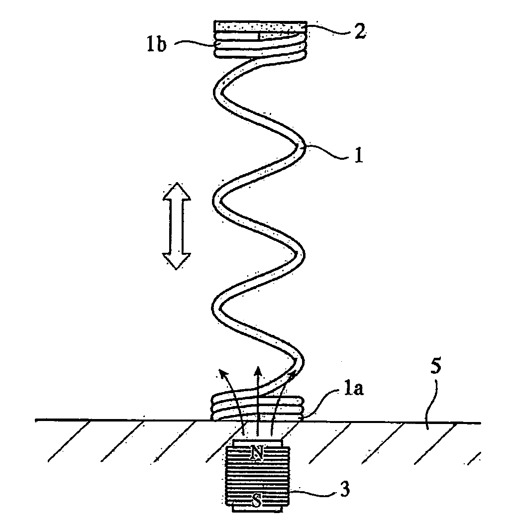
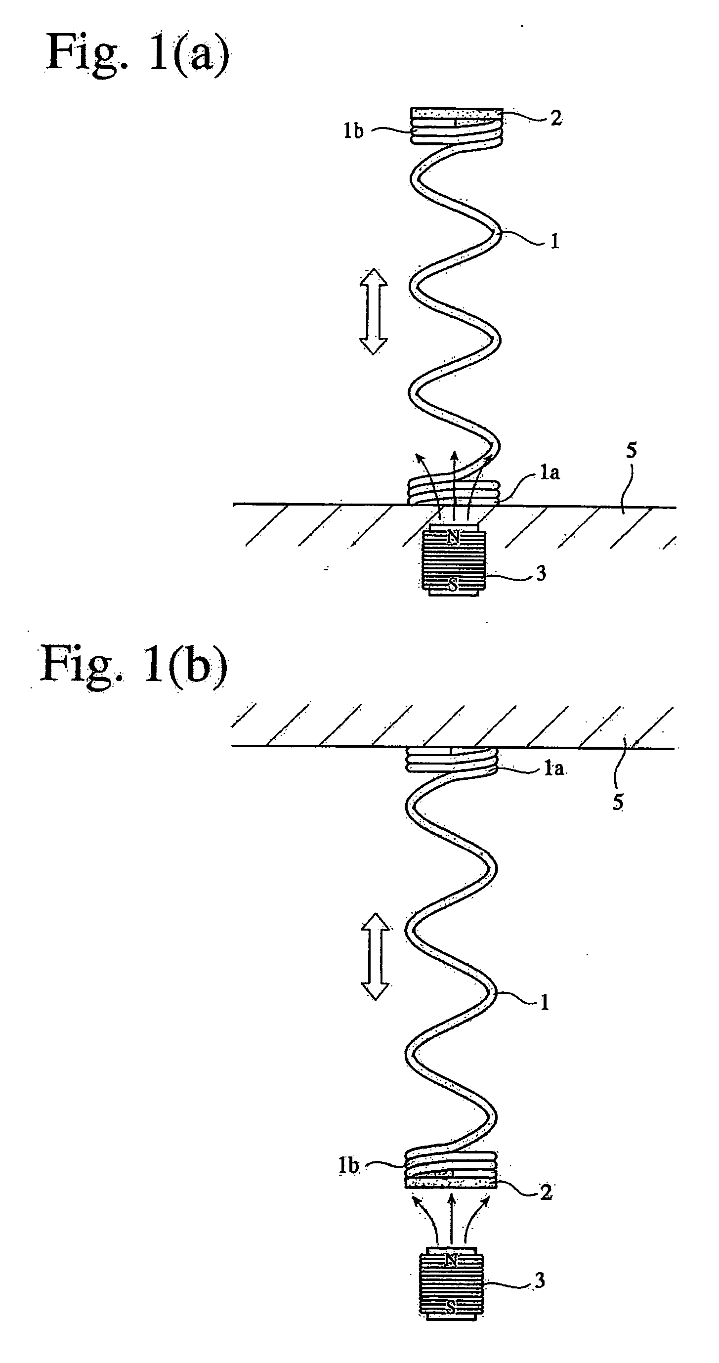
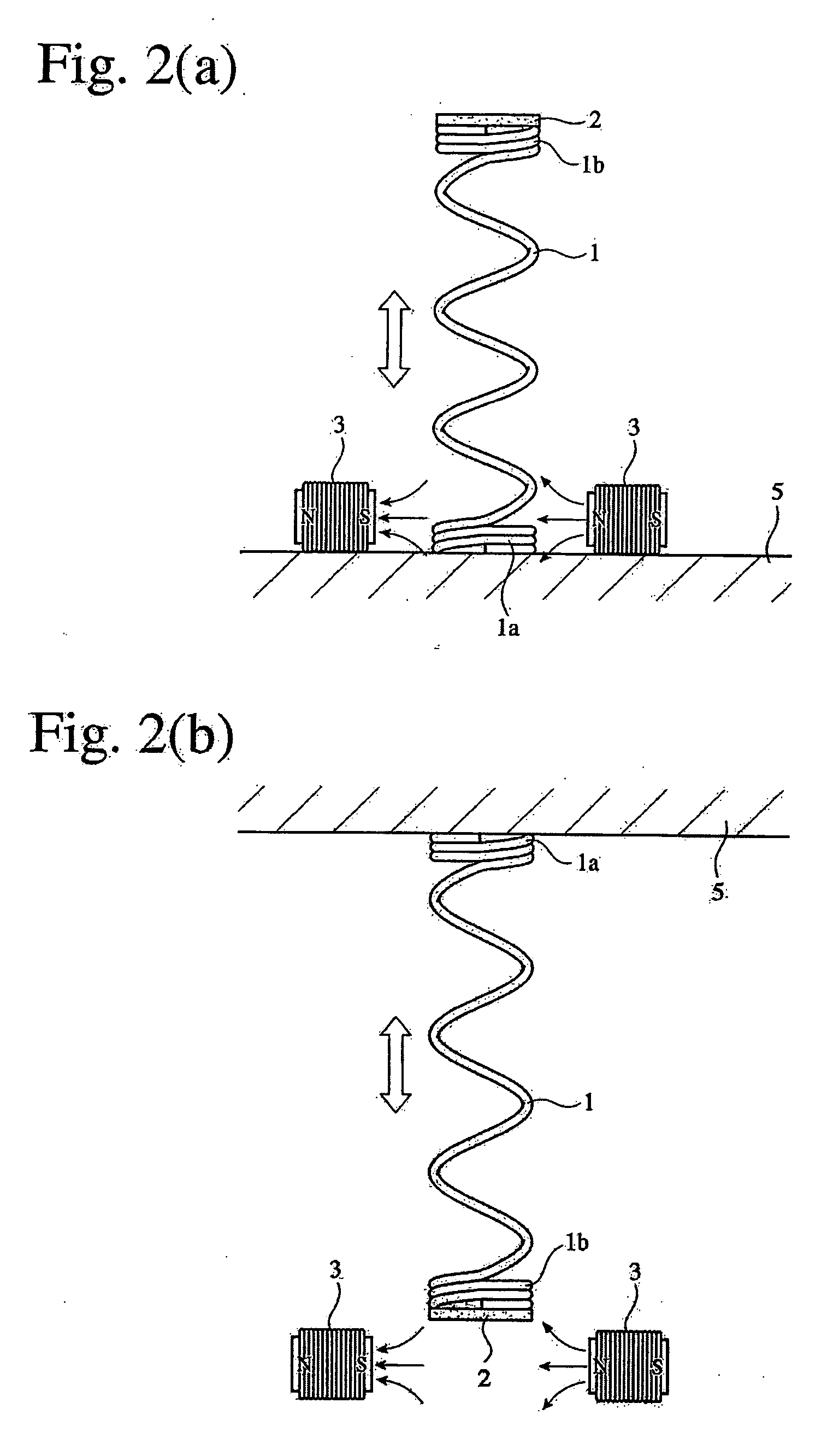
[0129] A cylindrical magnetic body 2 (diameter: 11 mm, height: 10 mm) made of an Fe—Co alloy (51 atomic % Fe) was attached to one end of the coil spring, and electromagnetic coils 3 (number of turns: 1,200, diameter: 25 mm, length: 40 mm) were arranged as shown in FIG. 2(a), to produce an actuator. Current for energizing the electromagnetic coils 3 was increased to obtain the relation between a magnetic field generated and the displacement of the magnetic body 2. The results are shown in FIG. 23.

example 2

[0130] An actuator was produced in the same manner as in Example 1 except that the cylindrical magnetic body was not used and the entire coil spring was covered with a 200-μm-thick Fe—Ni alloy (44.6 atomic % Fe). The structure of the actuator obtained was substantially the same as that of FIG. 5. Current for energizing the electromagnetic coils 3 was increased to obtain the relation between a magnetic field generated and the displacement of the magnetic body 2. The results are shown in FIG. 24 by black triangles.


PUM

PropertyMeasurementUnit
lengthaaaaaaaaaa
diameteraaaaaaaaaa
heightaaaaaaaaaa

Abstract

An actuator has a resilient shape memory member 1 with superelasticity, a magnetic body 2, and a magnetic field generator 3. At least one of the magnetic body 2 and the magnetic field generator 3 is fixed to the resilient shape memory member 1 such that one of the magnetic body 2 and the magnetic field generator 3 is stationary while the other is movable, whereby the movable member is moved by a magnetic field provided from the magnetic field generator 3.

Description

FIELD OF THE INVENTION [0001] The present invention relates to a high-response actuator, which utilizes the superelasticity of a shape memory alloy and a magnetic force to move a movable member. BACKGROUND OF THE INVENTION [0002] In the fields of robots, working machines, automobiles, etc. using electromagnetic motors, the weight reduction of driving systems is demanded. However, because the output densities of the electromagnetic motors depend on their weight, only limited weight reduction is available in actuators comprising the electromagnetic motors. It has thus been desired to develop a small-sized, lightweight actuator capable of providing high output. [0003] Actuators should satisfy such conditions that movable members are displaced to desired positions by a driving force; that the movable members are surely returned to original positions in a nonoperative state; that sufficiently large output is provided to enable the movable members to move even under a large load; etc. Spr...

Claims


Application Information

Patent Timeline
Patent Type & Authority Applications(United States)
IPC IPC(8): H01F7/08H02K33/00H01L41/12
CPCH02K57/006H02K33/00H02K99/20
Inventor OHTA, MASAHIROSUKIGARA, TORU
Owner HONDA MOTOR CO LTD
Why Eureka
Try Eureka