Electronic apparatus including circuit board chassis

a technology of circuit board and chassis, which is applied in the direction of supporting structure mounting, casings/cabinets/drawers, casings with connectors and pcbs, etc., can solve problems such as circuit board 101/b> warping, and achieve the effect of preventing circuit board from warping

Active Publication Date: 2006-03-02
DENSO CORP
View PDF5 Cites 30 Cited by
  • Summary
  • Abstract
  • Description
  • Claims
  • Application Information

AI Technical Summary

Benefits of technology

[0011] With the present invention, it becomes possible to prevent the circuit board from warping due to thermal expansion or contraction when ambient temperature rises or falls, because the circuit board is held in the chassis by being applied with the biasing force such that the circuit board can be displaced in a direction parallel to the plane of the circuit board.
[0012] Accordingly with the present invention, it is possible to avoid a solder joint of the electronic component from being applied with excessive stress due to thermal expansion or contraction of the circuit board, and the electronic component therefore can have a long life.

Problems solved by technology

However, such conventional circuit board fixing techniques have a problem in that the circuit board 101 warps when ambient temperature changes as shown in FIG. 14, because the circuit board 101 is rigidly fixed to the chassis 102.

Method used


Image

  • Electronic apparatus including circuit board chassis
  • Electronic apparatus including circuit board chassis
  • Electronic apparatus including circuit board chassis

Examples


first embodiment

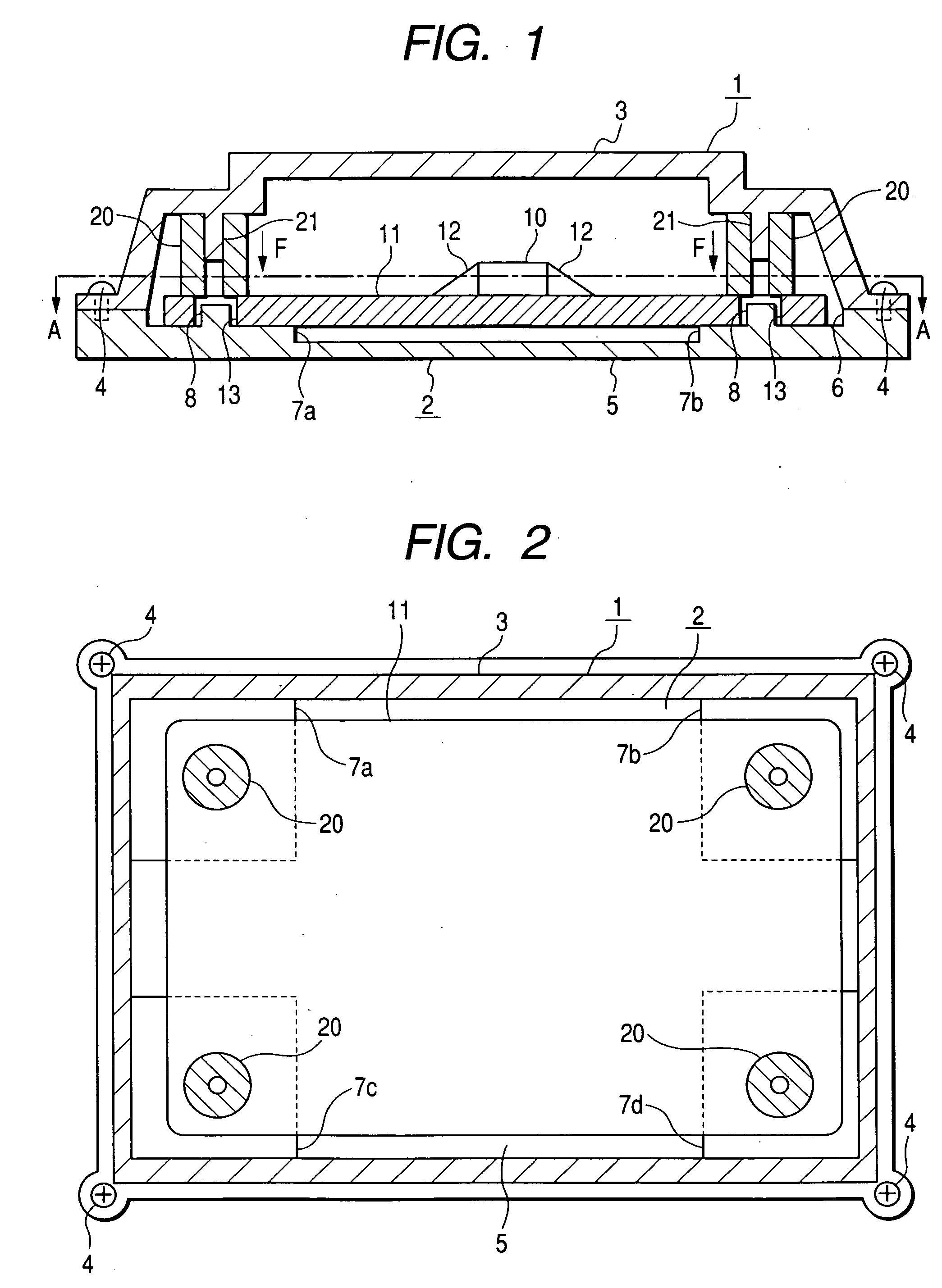
[0025]FIG. 1 is a longitudinal cross-sectional view of a chassis 1 of an electronic apparatus according to a first embodiment of the invention. As shown in this figure, the chassis 1, which is made of metal (iron or aluminum) or resin, includes a lower casing 2 serving as a base plate and an upper casing 3 serving as a cover. The lower casing 2 and the upper casing 3 are secured to each other by screws 4. A circuit board 11 on which an electronic component 10 is mounted by solder is housed in the chassis 1. In FIG. 1, reference numeral 12 denotes a solder joint of the electronic component 10. As a base material of the circuit board 11, a resin may be used. In this embodiment, the thermal expansion coefficient of the chassis 1 is larger than that of the circuit board 11.

[0026] Next, the detailed structure of the lower casing 2 is explained below.

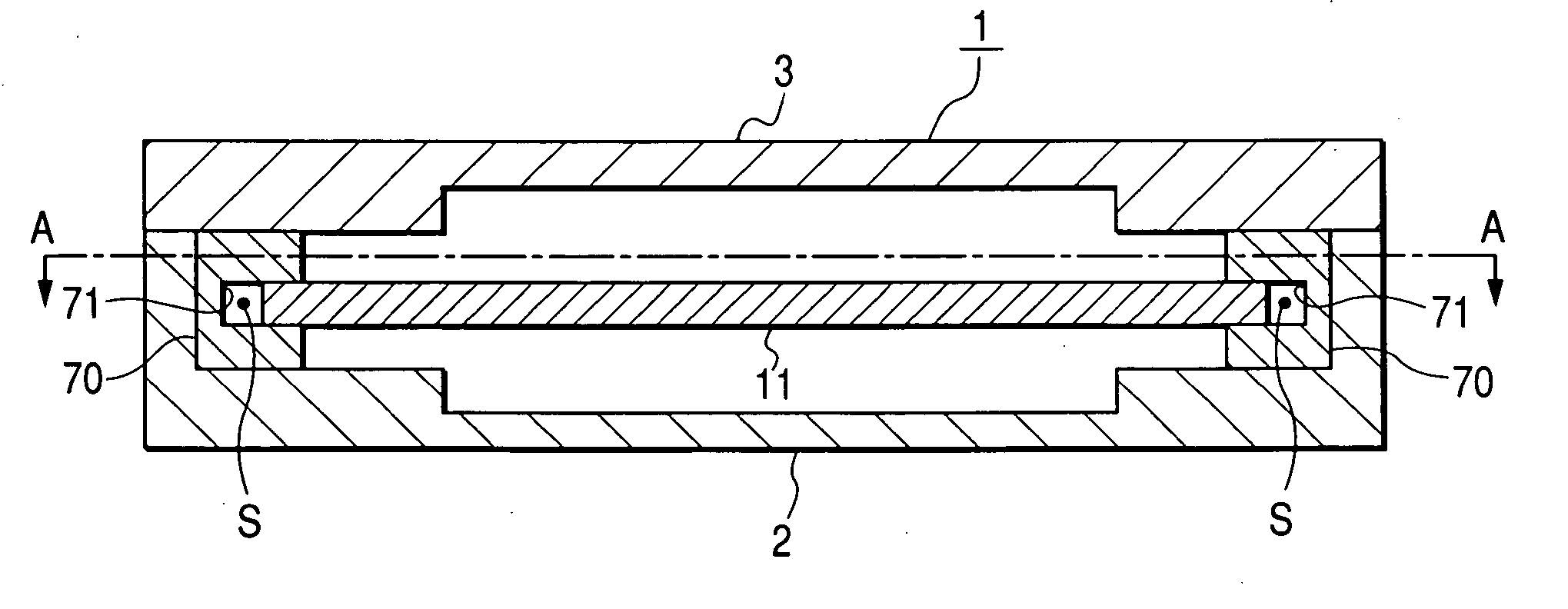
[0027] As shown in FIG. 1 and in FIG. 2 which is a horizontal cross-sectional view of the circuit board chassis 1 along the A-A line in FI...

second embodiment

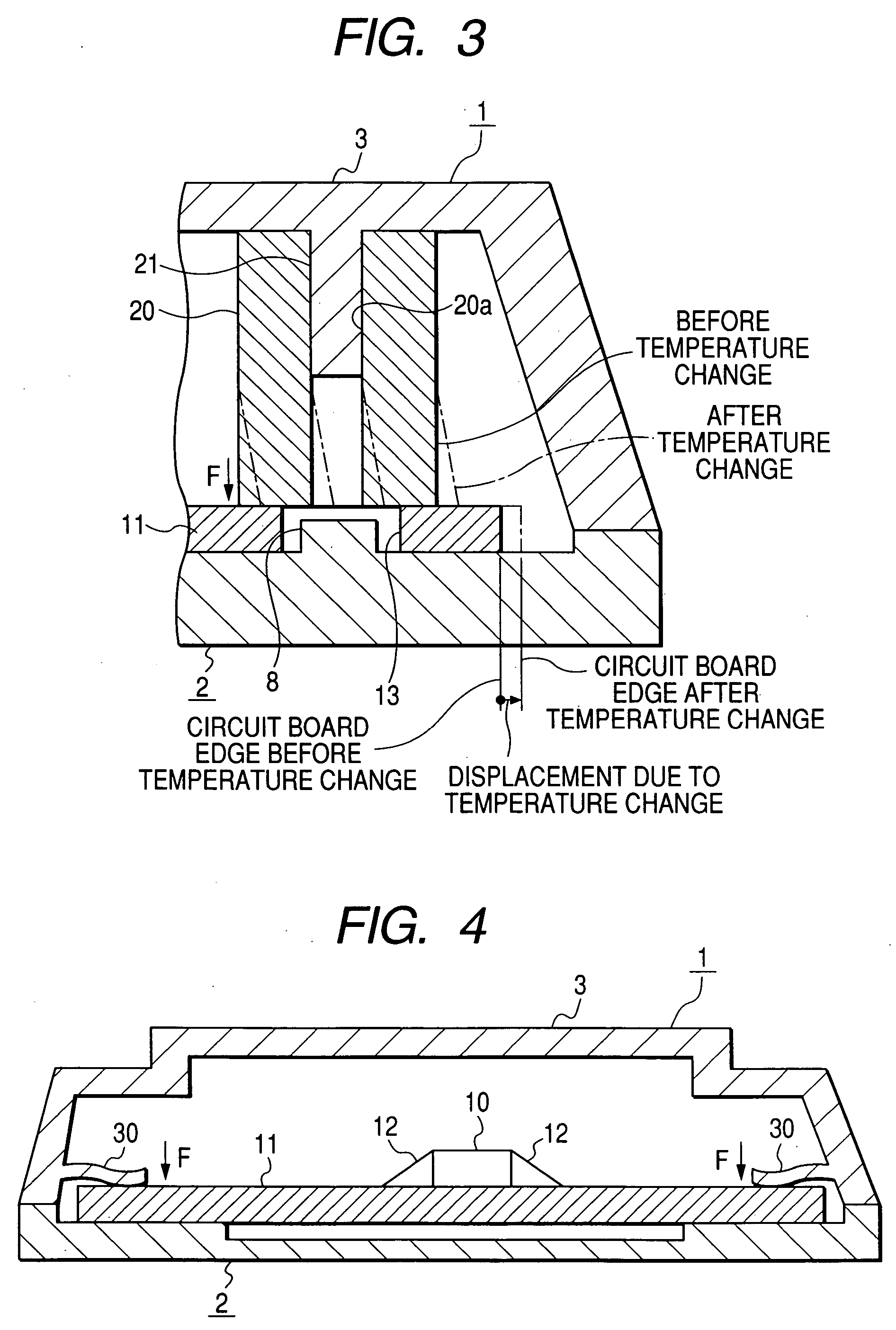
[0038]FIG. 4 is a longitudinal cross-sectional view of a chassis 1 of an electronic apparatus according to a second embodiment of the invention. The second embodiment is different from the first embodiment in that springs 30 are used instead of the elastic members 20.

[0039] The spring 30, which may be a blade spring, is formed so as to extend from the inner side surface of the upper casing 3 and abuts on the top surface of the circuit board 11. The spring 30 applies a downward biasing force F to the circuit board 11. The spring 30 can be press-formed in a case where the upper casing 3 is made of steel plate. The spring 30 can be formed integrally with the upper casing 3 in a case where the upper casing 3 is resin-molded. The spring 30 may be formed separately from the upper casing 3.

third embodiment

[0040]FIG. 5 is a cross-sectional view of a portion of a chassis 1 in the vicinity of one of elastic members 20 provided in the chassis 1 of an electronic apparatus according to a third embodiment. The third embodiment is characterized in that a smooth film 40 made of fluorocarbon resin (polytetrafluoroethylene, for example) is provided on the inner surface 2a of the lower casing 2 at areas contacting the bottom surface of the circuit board 11. The friction coefficient of the film 40 is smaller than that of the inner surface 2a of the lower casing 2.

[0041] In this embodiment, the circuit board 11 can expand or contract more easily when ambient temperature rises or falls than in the first embodiment. The third embodiment may be configured to have the positioning projections 8 and the through holes 13 as in the case of the first embodiment. The film 40 may be used in the second embodiment.


PUM


Abstract

The electronic apparatus includes a circuit board on which electronic component is mounted and a chassis housing the circuit board. The chassis is provided with a biasing force applying member applying a biasing force to at least one of top and bottom surfaces of the circuit board to hold the circuit board in position such that the circuit board is allowed to be displaced in a direction parallel to a plane of the circuit board.

Description

CROSS-REFERENCE TO RELATED APPLICATION [0001] This application is related to Japanese Patent Application No. 2004-247150 filed on Aug. 26, 2004, the contents of which are hereby incorporated by reference. BACKGROUND OF THE INVENTION [0002] 1. Field of the Invention [0003] The present invention relates to an electronic apparatus including a circuit board chassis. [0004] 2. Description of Related Art [0005] As a technique for fixing a circuit board 101 on which an electronic component 100 is mounted to a chassis 102, it is known to use screws 103 as shown in FIG. 11 (refer to U.S. Pat. No. 6,084,776, for example). It is also known to provide the chassis 102 with bent portions 110 by which the circuit board 101 is clamped as shown in FIG. 12. Fixing the circuit board 101 by use of an adhesive 120 as shown in FIG. 13 is also a well known technique. [0006] However, such conventional circuit board fixing techniques have a problem in that the circuit board 101 warps when ambient temperatur...

Claims


Application Information

Patent Timeline
Patent Type & Authority Applications(United States)
IPC IPC(8): H05K7/12
CPCH05K5/006H05K7/1417
Inventor MIZUTANI, AKIHIROUMEMOTO, SATORU
Owner DENSO CORP
Why Eureka
Try Eureka