
Vehicle oriented switched antenna system

Active Publication Date: 2006-03-02
DELPHI TECH INC
View PDF5 Cites 21 Cited by
  • Summary
  • Abstract
  • Description
  • Claims
  • Application Information

AI Technical Summary

Benefits of technology

[0008] In accordance with one aspect of the present invention, an antenna communication system is provided. The system includes a first antenna for communicating signals within a first directional coverage zone and a second antenna for communicating signals within a second directional coverage zone. According to one embodiment, the first and second antennas are located on a vehicle. The

Problems solved by technology

When the antenna employed has a weak signal, if the receiver switches to another antenna that exhibits a poorer quality signal or no signal, reduced antenna performance may be experienced.
This may result in a loss of information which, in an audio radio, can result in audio mute.

Method used


Image

  • Vehicle oriented switched antenna system
  • Vehicle oriented switched antenna system
  • Vehicle oriented switched antenna system

Examples


first embodiment

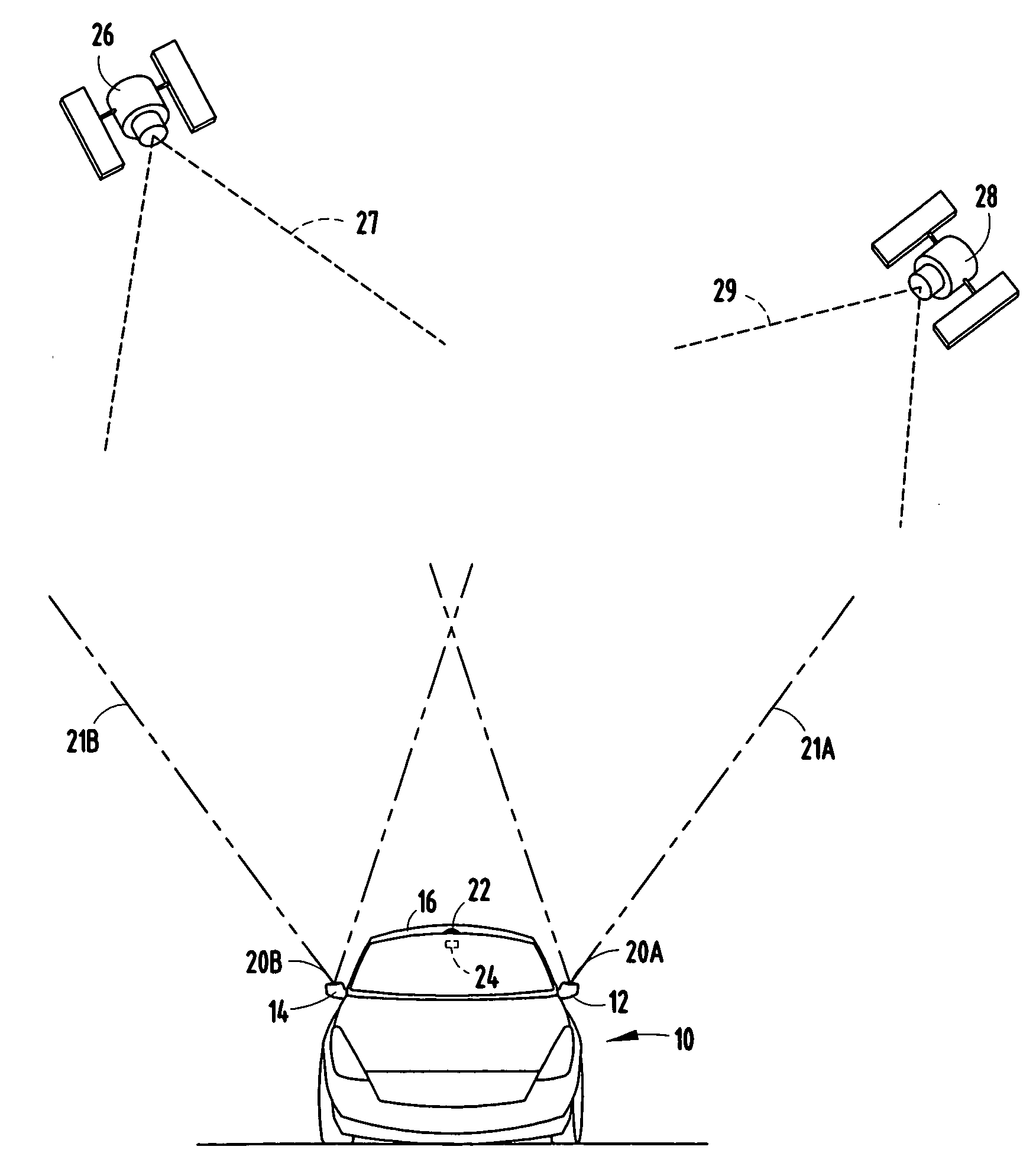
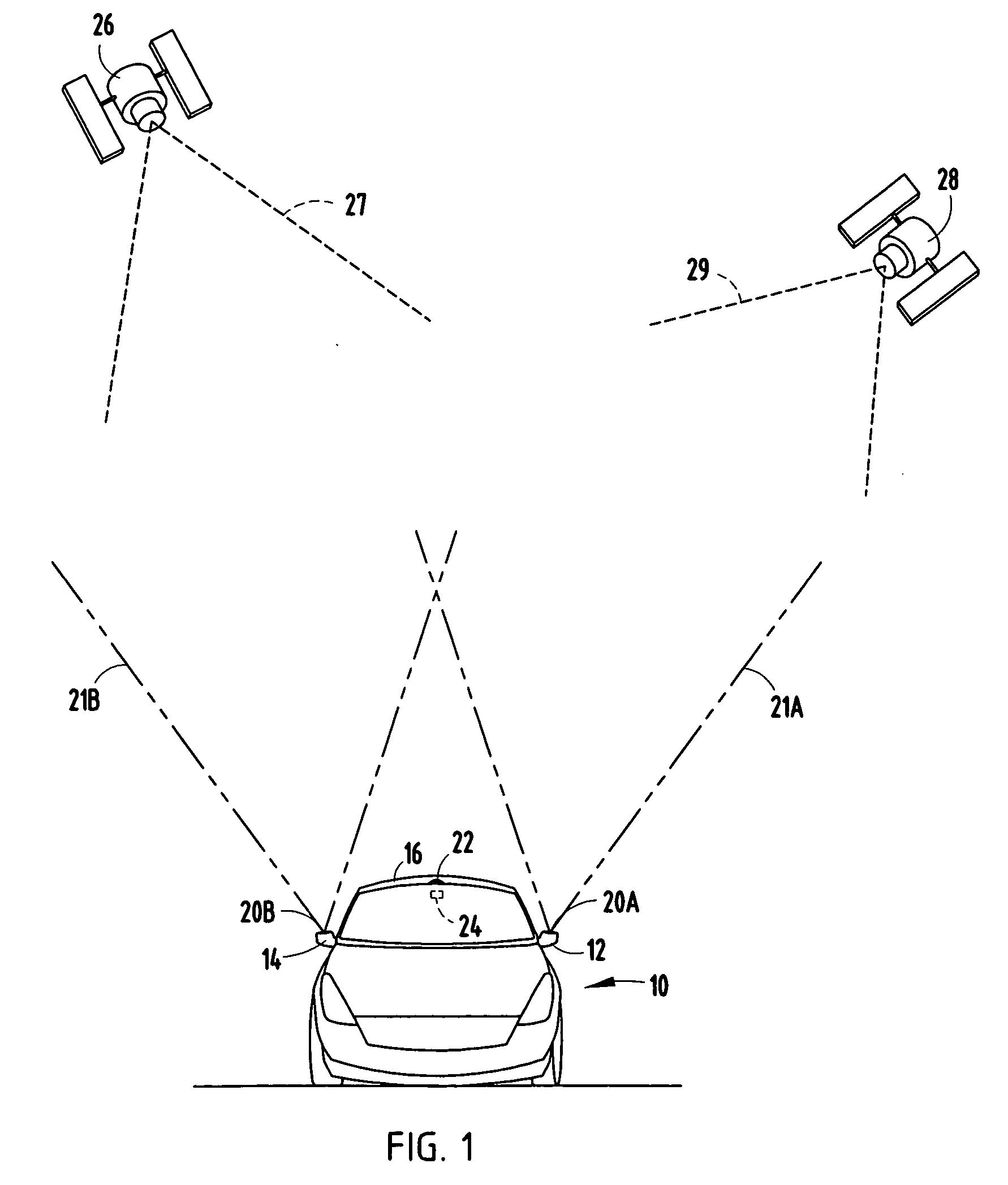
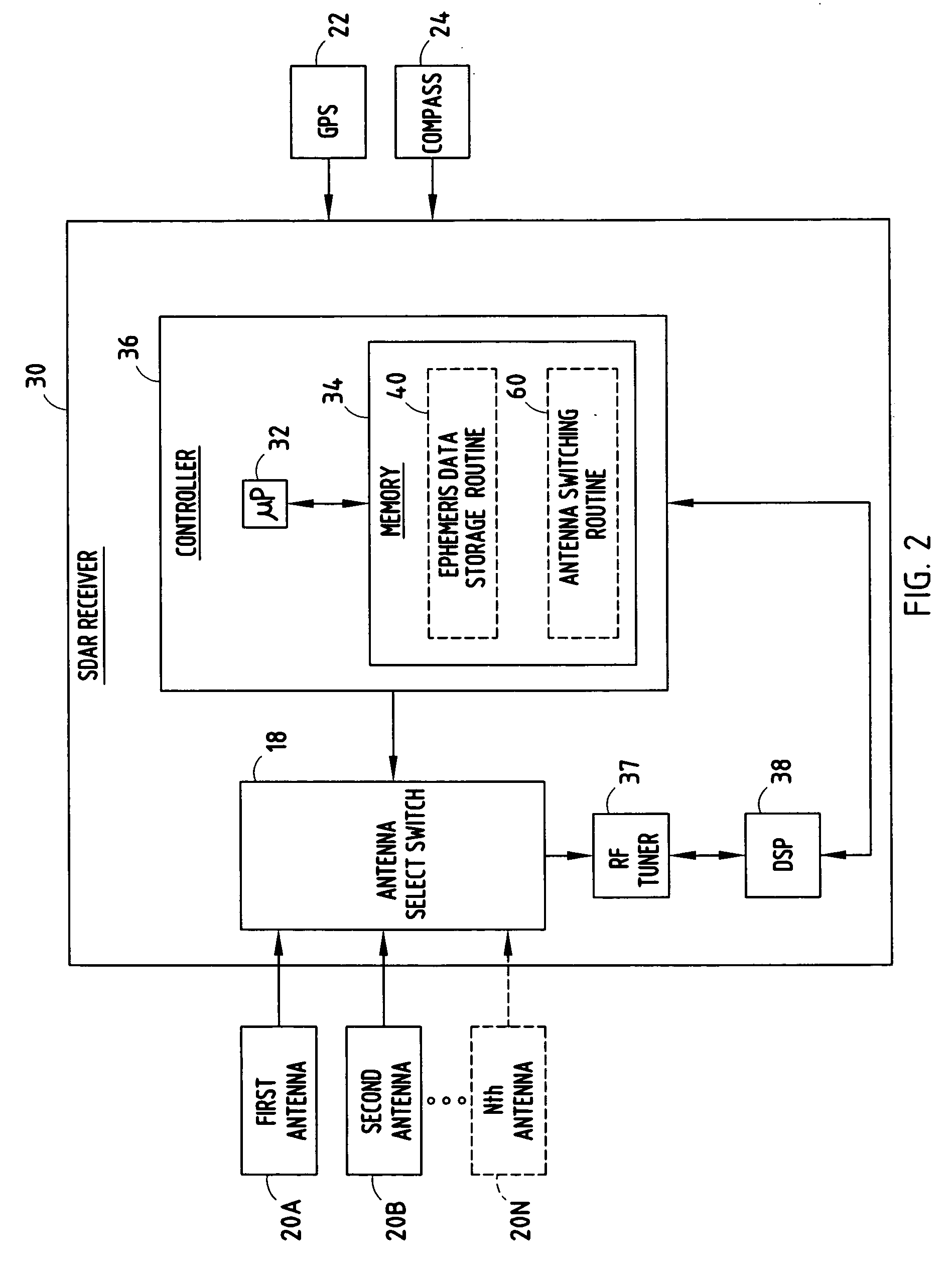
[0020] The vehicle 10 further includes an SDAR receiver 30 shown in FIG. 2 according to a The SDAR receiver 30 has inputs for receiving RF signals containing streams of broadcast data received from each of the antennas 20A-20N. The input signals from N number of antennas 20A-20N may be received via satellite or terrestrial based broadcast signals. The SDAR receiver 30 is further shown receiving signals from a global positioning system (GPS) 22 and a compass 24.

[0021] The SDAR receiver 30 is configured to receive digital signals from the antennas and process the digital signals, to selectively switch between the digital signals, and to process the selected digital signals. The receiver 30 includes an antenna select switch 18 for selecting which of the output signals from antennas 20A-20N to select for processing. Additionally, the receiver 30 includes an RF tuner 37 receiving the selected signals from one of antennas 20A-20N. The RF tuner 37 selects a frequency bandwidth of the digi...

second embodiment

[0024] Referring to FIG. 3, an antenna phase network 20′ is shown selectively controlled by receiver 30 according to a In this embodiment, the antenna phase network 20′ includes a plurality of antenna elements including elements 20A′-20N′, each of which alone or in combination may be considered an antenna. Each of the antenna elements 20A-20N are formed as a network that may be selectively controlled via a beam network 39 to control the beam pattern of the resultant antenna network. Each of the antenna elements 20A′-20N′ may be employed individually or selectively interconnected in a network by the beam network 39 to provide a plurality of distinct antenna patterns, each having a distinct antenna pattern to select from.

[0025] The SDAR receiver 30 shown in the second embodiment of FIG. 3 processes the same data as explained in connection with the first embodiment in FIG. 2, with the following exception. Instead of controlling an antenna select switch to select from multiple separate...


PUM


Abstract

An antenna system is provided having switched directional antennas. The antenna system includes a first antenna for receiving signals within a first directional coverage zone, and a second antenna for receiving signals within a second directional coverage zone. According to one embodiment, the first and second antennas are located on a vehicle. The system has a device to detect orientation of the vehicle. The system further includes a receiver having control circuitry for controlling selection of the signals received from the first and second antennas based on orientation of the vehicle, location of one or more sources, and antenna coverage zones for the first and second antennas.

Description

TECHNICAL FIELD [0001] The present invention generally relates to antennas and, more particularly, to a vehicle mounted antenna system and method of selectively communicating signals with remote transmission sources, such as satellites. BACKGROUND OF THE INVENTION [0002] Automotive vehicles are commonly equipped with various signal communication devices such as audio radios for receiving broadcast radio frequency (RF) signals, processing the RF signals, and broadcasting audio information to passengers in the vehicle. Satellite digital audio radio (SDAR) services have become available that offer digital radio service covering a large geographic area, such as North America. Currently, a couple of satellite-based digital audio radio services are available in North America. These SDAR services are referred to as Sirius satellite radio which employs three satellites in elliptical orbit and XM satellite radio which employs two satellites in geo-stationary orbit. Both services receive upli...

Claims


Application Information

Patent Timeline
IPC IPC(8): H04B1/00H04B7/185
CPCH04B7/18519
Inventor WALKER, GLENN A.MATEYCHUK, DUANE E.
Owner DELPHI TECH INC
Learn More