
Apparatus and method for controlling a plant

a technology of apparatus and method, applied in the direction of electric controllers, ignition automatic control, instruments, etc., can solve the problems of impairing the above-described advantages, and affecting the output of the model and the actual output of the plant, and achieve the effect of steady state error

Inactive Publication Date: 2006-03-02
HONDA MOTOR CO LTD
View PDF8 Cites 1 Cited by
  • Summary
  • Abstract
  • Description
  • Claims
  • Application Information

AI Technical Summary

Benefits of technology

[0009] By including in the model expression the term in which the estimated disturbance value is multiplied by the model parameter, the estimated disturbance value is reflected in the input into the plant without being calculated by the model parameter. Thus, it can be prevented that the estimated disturbance value is influenced by a change of the model parameters. A steady state error that may occur due to a change of the estimated disturbance value can be suppressed.
[0010] According to one embodiment of the invention, the model parameters are identified so that an error between a model output that is calculated based on the model expression and an actual plant output is minimized.
[0012] According to one embodiment of the invention, the model parameter is identified by correcting the extracted scheduled model parameter so that an error between a model output that is calculated based on the model expression and an actual plant output is minimized.

Problems solved by technology

As a result, a steady state error may occur between an output of the model and an actual output of the plant.
However, such minimization may impair the above-described advantages.

Method used


Image

  • Apparatus and method for controlling a plant
  • Apparatus and method for controlling a plant
  • Apparatus and method for controlling a plant

Examples


example 1

[0071] Now, a principle of the present invention will be described referring to a first embodiment of the present invention. A structure of a control apparatus in accordance with the first embodiment is similar to FIG. 3. This embodiment differs from a conventional control described above in the calculation implemented by the adaptive disturbance observer 103 for calculating the estimated disturbance value c1 and in the calculation of the equivalent control input Ueq, which is performed the controller 104.

[0072] As described above, the occurrence of a steady state error is caused by the fact that the value obtained by dividing the estimated disturbance value c1 by the model parameter b1 is reflected in the control input Ucain. In other words, a steady state error occurs because the estimated disturbance value c1 is not directly reflected in the control input Ucain, but is reflected in the control input Ucain with being influenced by the model parameter b1.

[0073] In order to remove...

example 2

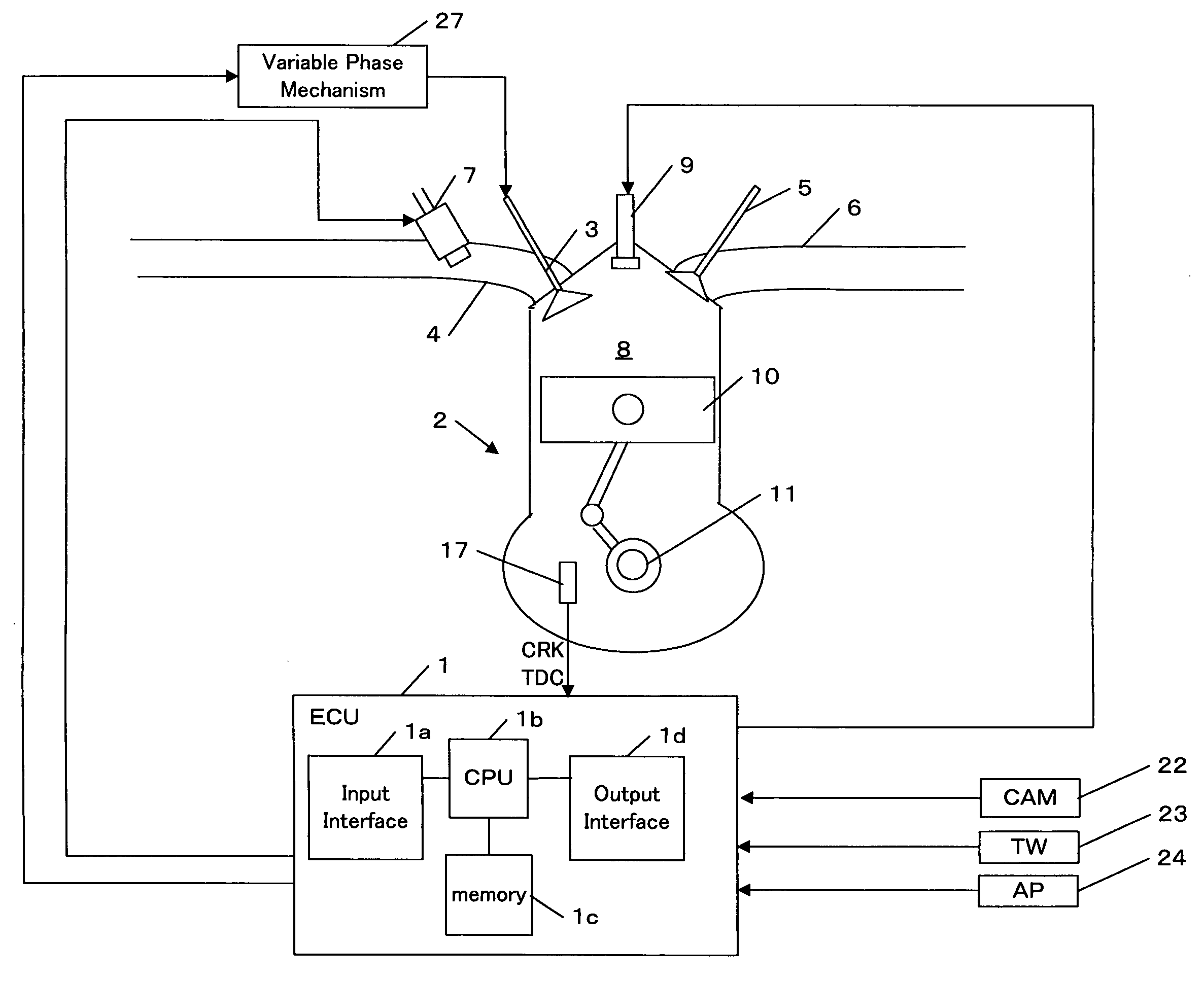
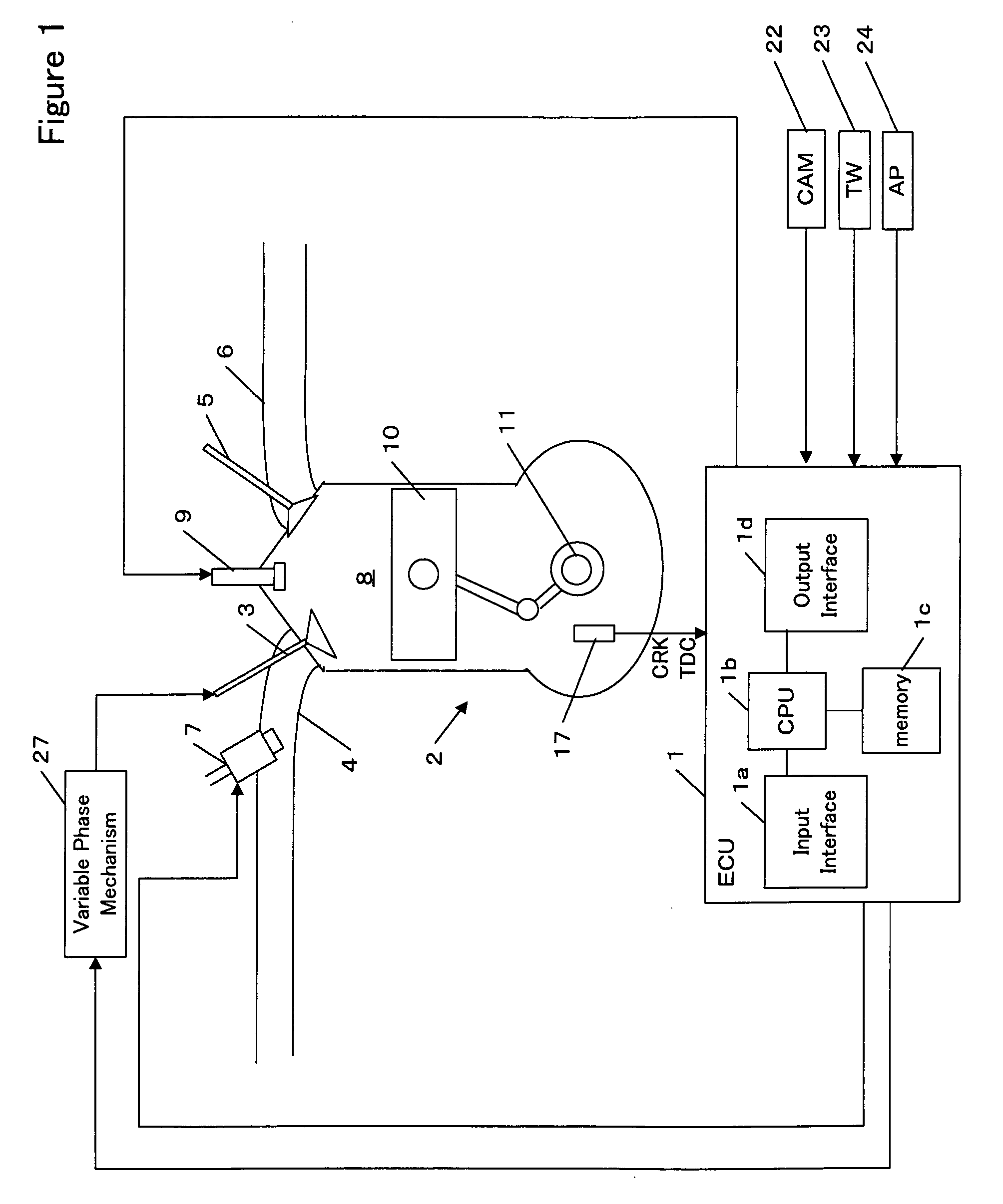
[0084]FIG. 8 is a block diagram of a control apparatus in accordance with a second embodiment of the present invention. As with the first embodiment, the functions of a scheduler 112, on-board identifier 113 and controller 114 can be implemented in the ECU 1.

[0085] Model parameters corresponding to the operating condition of the engine are stored as a table or a map in the memory 1c of the ECU 1. One example of such a map is shown in FIG. 9(a). A scheduler 112 refers to the map based on a detected engine rotational speed NE to extract scheduled model parameters a1sc—map, a2sc—map, b1sc—map, b2sc—map and c1sc—map corresponding to the engine rotational speed NE. As shown in the equations (2-1) and (2-2), the scheduler 112 substitutes the extracted scheduled model parameters a1sc—map and a2sc—map into model parameter reference values a1sc and a2sc, respectively. The scheduler 112 further extracts a gain Kbsc by referring to a map as shown in FIG. 9(b) based on the detected phase CAIN....

example 3

[0097]FIG. 10 is a block diagram of a control apparatus in accordance with a third embodiment of the present invention. As with the above embodiments, the functions of a scheduler 122, partial model parameter identifier 123 and controller 124 can be implemented in the ECU 1.

[0098] Model parameters corresponding to the operating condition of the engine are stored as a table or a map in the memory 1c of the ECU 1. A map as shown in FIG. 9(a) can be used for this embodiment. A scheduler 122 refers to the map based on a detected engine rotational speed NE to extract scheduled model parameters a1sc—map, a2sc—map, b1sc—map, b2sc—map and c1sc—map corresponding to the engine rotational speed NE. As shown in the equations (3-1) and (3-2), the scheduler 122 substitutes the extracted scheduled model parameters a1sc—map and a2sc—map into model parameters a1 and a2, respectively. The scheduler 122 further extracts a gain Kbsc by referring to a map as shown in FIG. 9(b) based on the detected pha...


PUM


Abstract

A control for a modeled plant is provided. The modeled plant is represented by a model expression that is based on an input into the plant, an output from the plant, model parameters, and an estimated value for disturbance that is applied to the plant. The model expression includes a term in which the estimated disturbance value is multiplied by at least one of the model parameters. The model parameters are identified. The estimated disturbance value is calculated so that an error between a model output that is calculated based on the model expression and an actual output of the plant is minimized. The input into the plant is calculated based on the model expression so as to control the plant. Thus, the estimated disturbance value is directly reflected in the input into the plant without being calculated by any of the model parameters.

Description

BACKGROUND OF THE INVENTION [0001] The present invention relates to an apparatus and method for controlling a plant. [0002] Several techniques for controlling an object modeled using a model parameter (such an object is also called a plant) have been proposed. Considering disturbance that may be applied to the plant, an estimated value of the disturbance (which will be hereinafter referred to as an estimated disturbance value) can be included in the model expression for the plant. [0003] According to a control technique described in Japanese Patent Application Publication No. 2003-5804, reference values for the model parameters, including the above estimated disturbance value, are scheduled in accordance with an engine condition parameter (for example, a throttle valve opening) that is in a correlation with the model parameters. An identifier, which is introduced in a control apparatus, recursively identifies the model parameters and the estimated disturbance value based on the sche...

Claims


Application Information

Patent Timeline
Patent Type & Authority Applications(United States)
IPC IPC(8): G05B11/01
CPCG05B5/01G05B17/02G05B13/042
Inventor YASUI, YUJI
Owner HONDA MOTOR CO LTD
Learn More