
Apparatus and method for controlling current

a current control and apparatus technology, applied in the field of proportional resonance (pr) control apparatus, can solve the problems of components over a specific frequency that are uncontrollable, steady-state error with respect, and the cut-off frequency of the closed loop control system cannot be infinitely increased, so as to achieve the effect of harmonic current control performance and improve harmonic control performan

Active Publication Date: 2018-10-04
LSIS CO LTD
View PDF4 Cites 0 Cited by
  • Summary
  • Abstract
  • Description
  • Claims
  • Application Information

AI Technical Summary

Benefits of technology

This patent describes an apparatus that acts as a secondary band-pass filter to control harmonic current in an inverter system. The apparatus helps reduce steady-state errors and can achieve effective harmonic control performance with low switching frequencies. The system can also improve harmonic compensation or dead time compensation.

Problems solved by technology

However, the cut-off frequency of the closed loop control system cannot be infinitely increased because it is limited by a switching frequency of an inverter.
Therefore, in an inverter with a low switching frequency, the steady-state error is caused with respect to a high frequency component upon a harmonic current compensation.
Therefore, since the PR control apparatus is typically configured to compensate only for limited harmonic current, components over a specific frequency is uncontrollable.

Method used


Image

  • Apparatus and method for controlling current
  • Apparatus and method for controlling current
  • Apparatus and method for controlling current

Examples


first embodiment

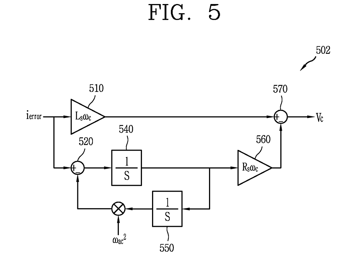
[0031]FIG. 5 is a detailed configuration view of a transfer function application unit according to a

[0032]Referring to FIG. 5, a current control apparatus according to a first embodiment includes a transfer function application unit 502. At this time, the current control apparatus operates similar to a primary low-pass filter having a cut-off frequency ωc. At this time, the transfer function application unit 502 applies a gain including the cut-off frequency ωc to a current error ierror. The transfer function application unit 502 includes a first applying portion 510, a first calculating portion 520, a second calculating portion 530, a first integrating portion 540, a second integrating portion 550, a second calculating portion 560 and a third calculating portion 570.

[0033]The first applying portion 510 applies a first gain Lsωc to a current error ierror. At this time, the first gain Lsωc is decided according to an inductance component Ls of the plant 110 and a cut-off frequency ωc....

second embodiment

[0038]FIG. 6 is a configuration view of a current control apparatus in accordance with a

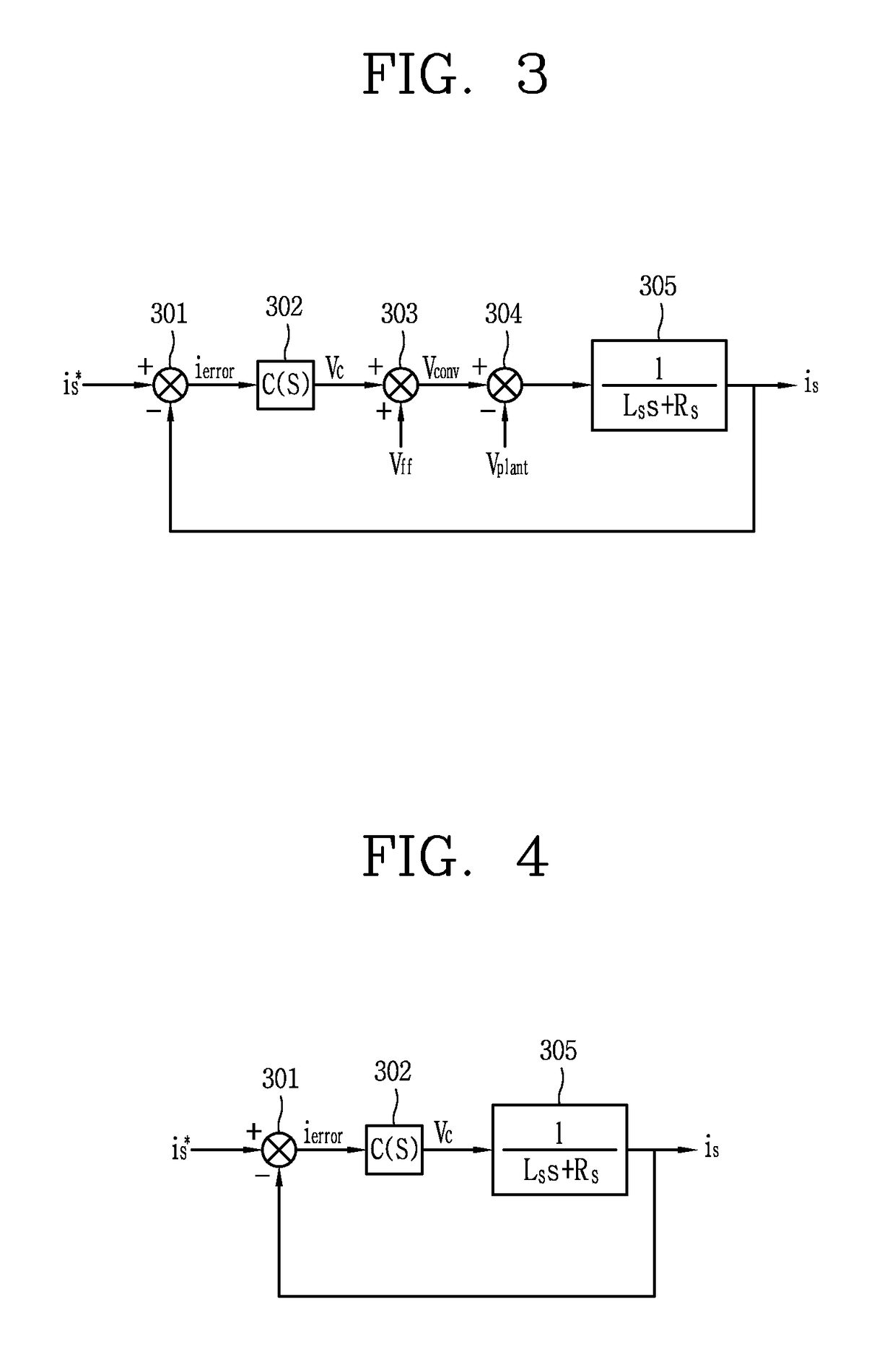
[0039]Referring to FIG. 6, a current control apparatus 600 according to a second embodiment includes a comparison unit 601, a transfer function application unit 602, and a calculation unit 603. The comparison unit 601 outputs a current error ierror between a current command is* and an output current is of the plant 110. The transfer function application unit 602 outputs an output voltage Vc by applying a first transfer function of a feedback component into the current error ierror. The calculation unit 603 outputs an output current is by applying a second transfer function to the output voltage Vc. The second transfer function is decided based on an inductance component Ls of the plant 110 and a loss resistance component Rs of the plant 110.

[0040]At this time, the current control apparatus 600 operates like a secondary band-pass filter, which uses a control frequency ωac of the current command as...


PUM


Abstract

The present invention relates to an apparatus for controlling an output current provided from an inverter to a plant according to a current command. The apparatus includes a calculation unit to decide a current error between the current command and the output current, output an output voltage by applying a gain including a control frequency of the current command to the current error, and output an output current from the output voltage.

Description

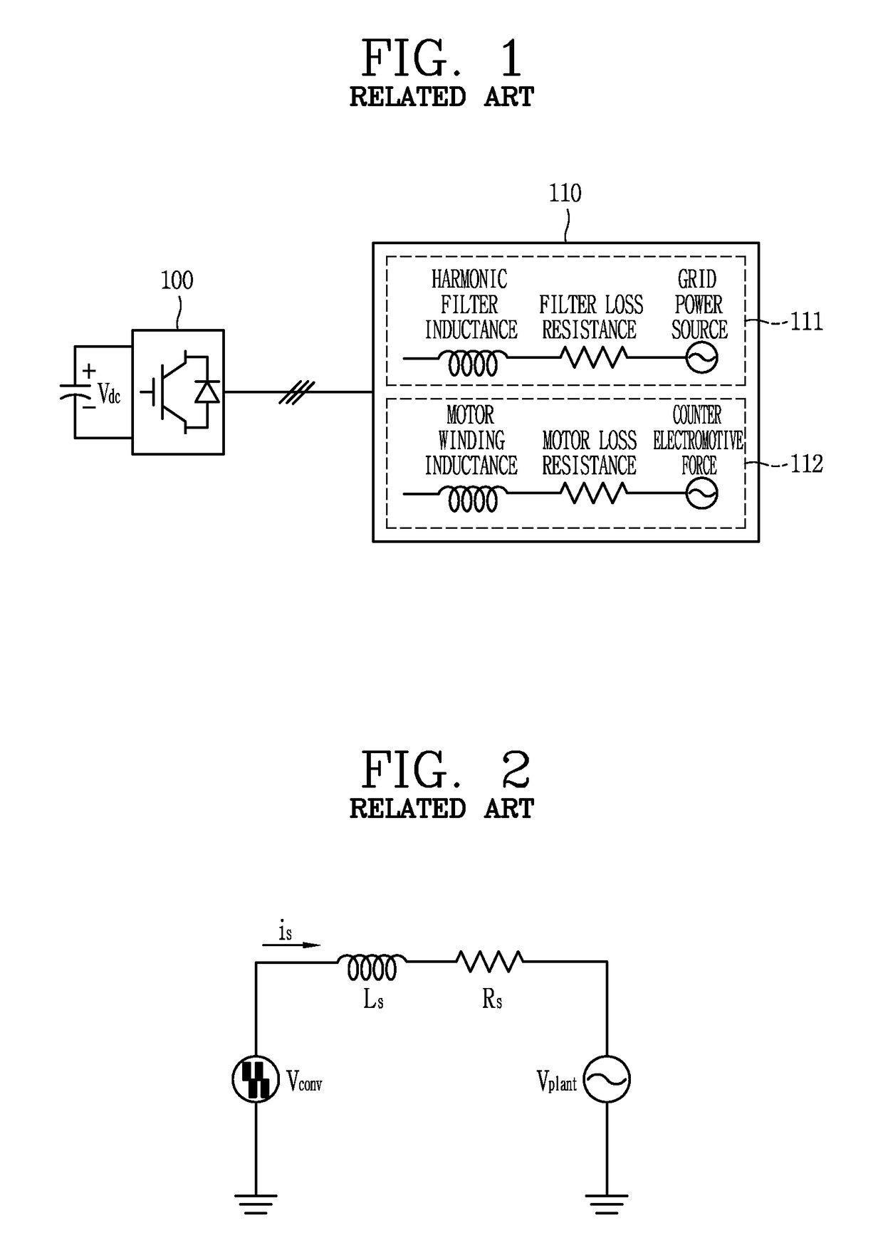
CROSS-REFERENCE TO RELATED APPLICATION[0001]Pursuant to 35 USC § 119 (a), this application claims the benefit of an earlier filing date and priority to Korean Application No. 10-2017-0038962, filed on Mar. 28, 2017, the contents of which are incorporated by reference herein in its entirety.BACKGROUND OF THE INVENTION1. Field of the Invention[0002]Various embodiments relate to an apparatus and method for controlling current, and more particularly a proportional resonance (PR) control apparatus and an operating method thereof.2. Description of the Related Art[0003]Generally, a proportional and resonant (PR) control apparatus for controlling current is implemented on a stationary coordinate system of a single-phase or three-phase system to control alternating current, and is widely used in industry.[0004]Since the PR control apparatus theoretically has an infinite gain for a specific frequency, it has similar characteristics to those of a primary low-pass filter, in which a transfer fu...

Claims


Application Information

Patent Timeline
IPC IPC(8): H01H71/24
CPCH01H71/2472G05F1/12H02M1/12G05F1/565H02M7/48H02M1/126H02J3/01Y02E40/40
Inventor CHO, BYUNGGEUK
Owner LSIS CO LTD
Learn More