
Residual feedback to improve estimator prediction

a technology of estimator prediction and feedback, applied in the field of control system theory, can solve the problems of model prediction error, steady-state error in predictions, etc., and achieve the effect of substantially eliminating steady-state error and eliminating steady-state error in predicted states

Inactive Publication Date: 2005-11-22
TEXAS INSTR INC
View PDF6 Cites 1 Cited by
  • Summary
  • Abstract
  • Description
  • Claims
  • Application Information

AI Technical Summary

Benefits of technology

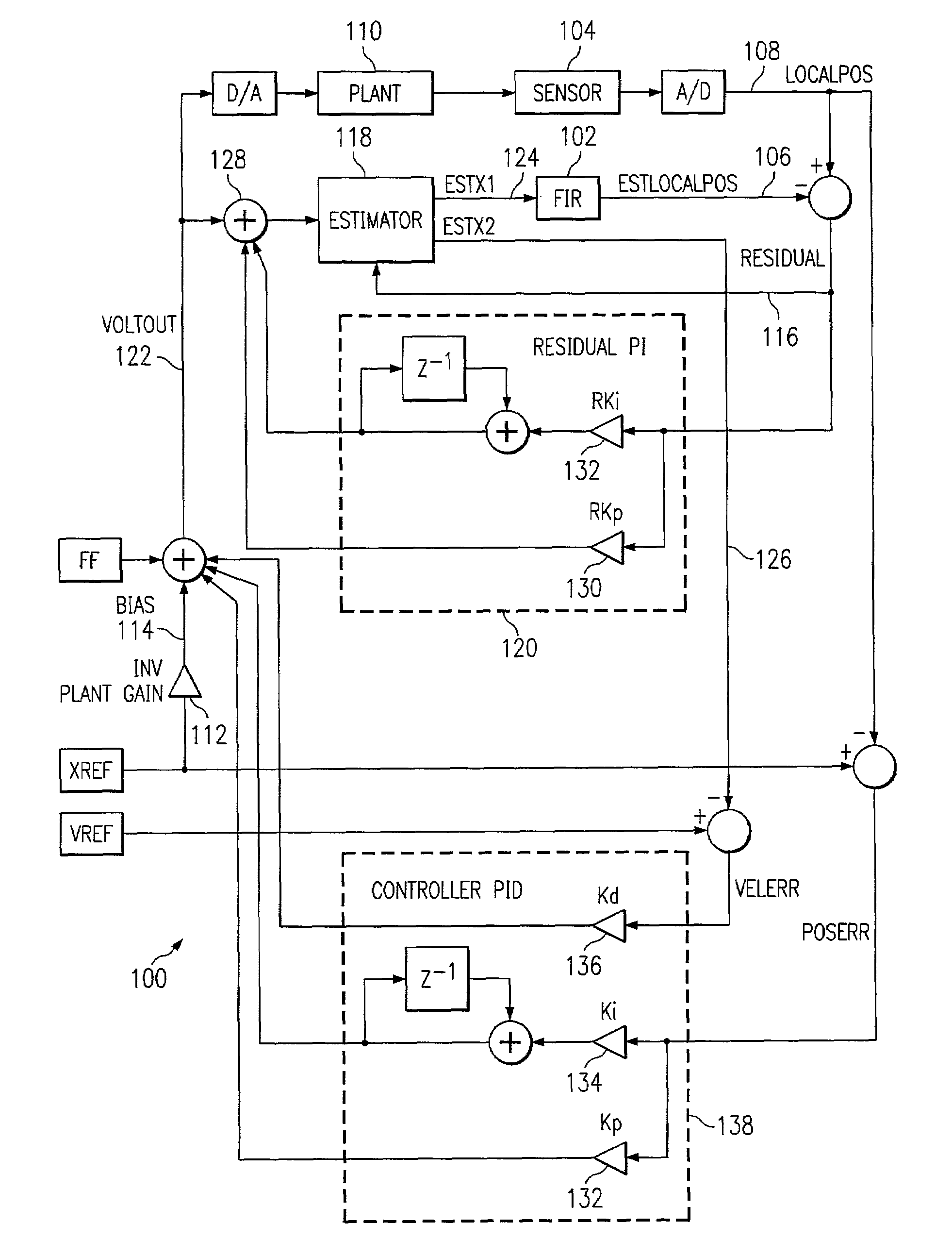
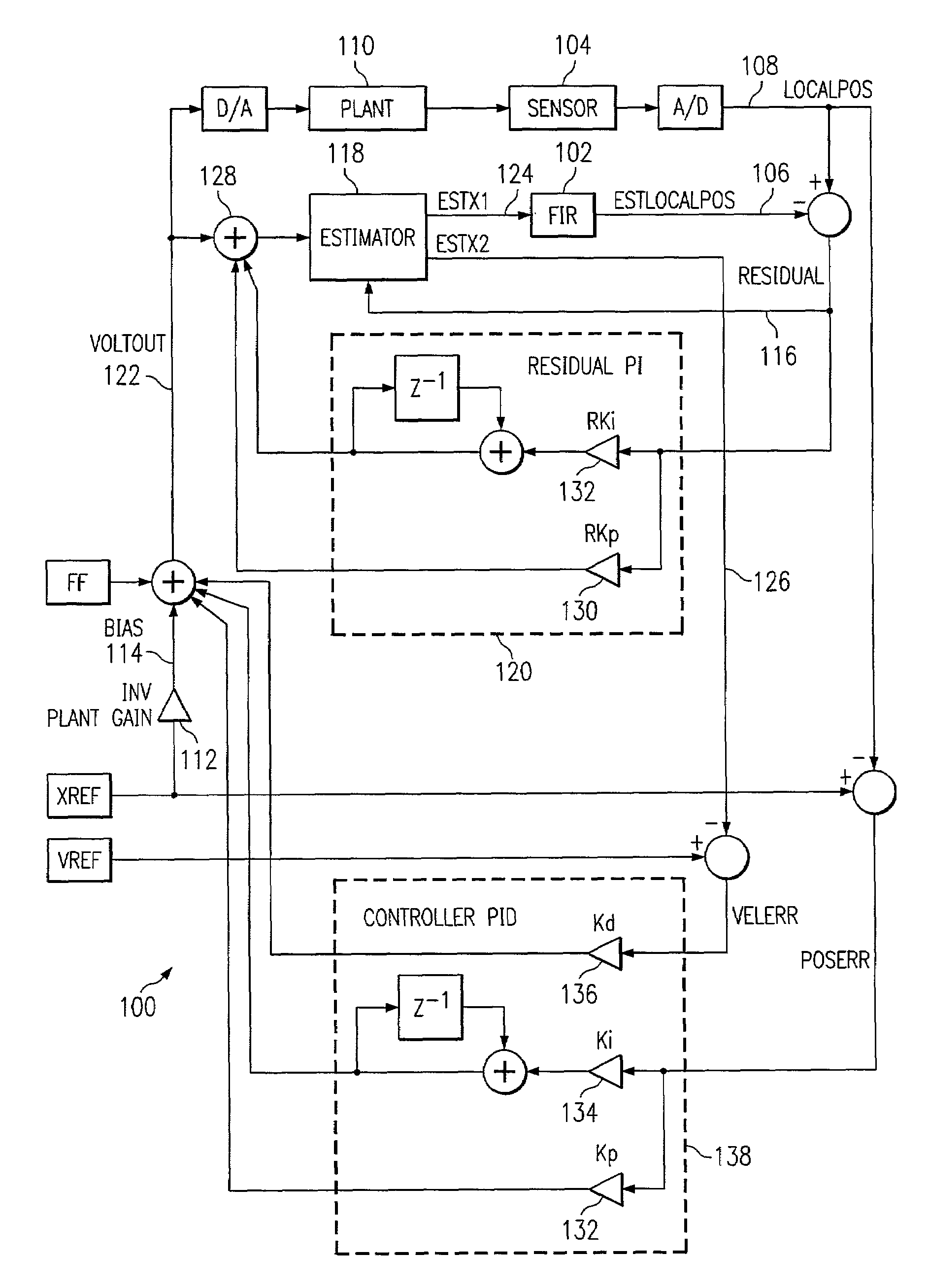
[0008]The present invention is directed to a method of using residual feedback in a control loop in a manner that substantially eliminates the steady state error in the predicted states that results from the mismatch in gain between the physical plant and the estimator model. The control effort used by the estimator to predict the next position is modified to compensate for this mismatch in gain. By integrating the residual, and modifying the apparent control effort accordingly, the residual is driven to have a mean value of zero. When the residual goes to zero, by definition, the steady state error in the position goes to zero; and if the model is accurate, the velocity state will also approach zero such that the steady state error in the predicted states are substantially eliminated.

Problems solved by technology

This model predicts what the position (X1) and velocity (X2) should be for a given control effort; and due to a variety of sources, the model will have some error in the predictions.
Predictions associated with MEM mirrors are problematic however, in that the model is basically a spring; so a mismatch in the model results in a steady-state error in the predictions.
When the residual correction is made, the result is a steady state error in the predicted states.
This steady state error can cause an undesirable transient response.
When using feedback to move the mirror from one angular location to another (hereto referred to as seeks) however, the large required integrator value will change; and although it will eventually reach its final value, it takes many samples to do so.
While it is converging however, the control effort is also changing and the position is not held very tightly.
The root of this problem is a mismatch in gain between the model and the mirror.

Method used


Image

  • Residual feedback to improve estimator prediction
  • Residual feedback to improve estimator prediction

Examples


Embodiment Construction

[0016]The particular embodiments of the invention described herein below are best understood by first reiterating the discussion of the problem to be solved set forth herein before. An estimator-based controller associated with MEM mirror movements contains a mathematical model of the mirror. This model predicts what the position and velocity should be for a given control effort; and due to a variety of sources, the model will have some error in the predictions. A standard textbook method of correcting for prediction mismatch is to calculate the “residual”, the difference between the predicted and measured position, and then feed that error back into the underlying states using the following equations.

X1=X1+(L1*Residual)

X2=X2+(L2*Residual)

[0017]Predictions associated with systems having a large bias force which is dependant on position, a MEM mirrors for example, are problematic however, in that a mismatch in the model results in a steady-state error in the predictions. When the res...


PUM


Abstract

A system and method 100 of using residual feedback in a control loop in a manner that substantially eliminates the steady state error in the predicted states that results from the mismatch in gain between the plant and the model. The control effort used by the estimator to predict the next position is modified to compensate for this difference in gain. By integrating the residual, and modifying the apparent control effort accordingly, the residual is driven to have a mean value of zero. When the residual goes to zero, by definition, the steady state error in the position state goes to zero; and to the extent that the model matches the plant, the velocity state also approaches zero such that the steady state error in the predicted states are substantially eliminated, allowing for improved control.

Description

BACKGROUND OF THE INVENTION[0001]1. Field of the Invention[0002]This invention relates generally to control system theory, and more particularly, to a method of controlling a micro-electro-mechanical MEM mirror motion.[0003]2. Description of the Prior Art[0004]An estimator-based controller associated with micro-electro mechanical system (MEMS) mirror movements contains a mathematical model of the mirror. This model predicts what the position (X1) and velocity (X2) should be for a given control effort; and due to a variety of sources, the model will have some error in the predictions. A standard textbook method of correcting for prediction mismatch is to calculate the “residual”, the difference between the predicted and measured position, and then feed that error back into the underlying states using the following equations, where L1 and L2 determine the extent to which the residual error should affect the state variables X1 and X2.X1=X1+(L1*Residual)X2=X2+(L2*Residual)[0005]Predicti...

Claims


Application Information

Patent Timeline
Patent Type & Authority Patents(United States)
IPC IPC(8): G05B11/42G05B13/04
CPCG05B11/42G05B13/048
Inventor OETTINGER, ERIC G.
Owner TEXAS INSTR INC
Learn More