Control system and method for laser radar galvanometer servo motor

A servo motor and control system technology, applied in general control systems, control/adjustment systems, computer control, etc., can solve the problems of no advantages in speed and precision indicators, complex neural network control, and low speed indicators, etc., and reach the target area range The effect of wide, fast response and large scanning angle

Active Publication Date: 2019-01-18
NANJING UNIV OF SCI & TECH
View PDF6 Cites 8 Cited by
  • Summary
  • Abstract
  • Description
  • Claims
  • Application Information

AI Technical Summary

Problems solved by technology

The PID adjustment method is the most widely used in technology, but it is also the most inaccurate control; fuzzy control does not control a specific model, although it is universal, but has no advantages in speed and accuracy indicators; neural network control is very complicated, resulting in The speed index is not high, and it is only suitable for high-precision control schemes

Method used


Image

  • Control system and method for laser radar galvanometer servo motor
  • Control system and method for laser radar galvanometer servo motor
  • Control system and method for laser radar galvanometer servo motor

Examples


Embodiment 1

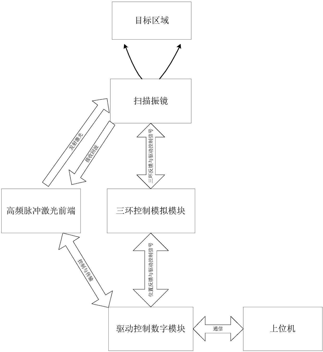
[0062] This embodiment is aimed at the control system of the laser radar galvanometer servo motor, including:

[0063] 1) Select the high-frequency pulse laser front end to generate high-frequency laser, and use a high-sensitivity detector to receive the laser ranging echo;

[0064] 2) Use the scanning galvanometer to change the laser light path, and periodically scan the designated area;

[0065] 3) Send the obtained laser beam position and target distance information to the host computer through the drive control digital module;

[0066] 4) The host computer draws the point cloud image of the designated area through the 3D reconstruction software.

[0067] The servo drive control system is composed of a drive control digital module and a three-loop control analog module, and the drive control digital module is composed of ARM and FPGA. The drive control digital module has the functions of generating drive signals, processing feedback signals, judging system status, and sel...


PUM


Abstract

The invention discloses a control system and method for a laser radar galvanometer servo motor. The system comprises an upper computer, a drive control digital module, a three-loop control analog module, a high-frequency pulse laser front end and a scanning galvanometer, and the drive control digital module comprises a main control ARM unit and an FPGA unit, which are connected with each other. The method comprises the following steps: after the galvanometer servo motor starts to work smoothly, judging whether the system performs scanning in a working mode with the highest performance, judgingthe mode according to a set threshold, and adopting two index improvement methods: in a smooth speed running mode, importing an interpolation module to improve the resolution of a control signal so as to achieve the purpose of high-precision scanning; and in a high-speed scanning mode, importing a repeated tracking accumulated error control unit to perform error collection and correction for multiple cycles so as to achieve the purpose of improving the precision. The control system disclosed by the invention ensures stable and efficient operation of a high-precision three-dimensional imagingscanning system in a high speed state.

Description

technical field [0001] The invention relates to the laser radar vibrating mirror servo motor technology, in particular to a control system and method for the laser radar vibrating mirror servo motor. Background technique [0002] The galvanometer servo system is widely used, and it is very mature in industrial engineering fields such as laser marking and laser positioning, and it is also widely used in 3D scanning imaging systems. The optical scanning head of the galvanometer system is a position-following servo system. Its function is to change the deflection angle of the motor, and then change the optical path of laser emission and reception, and finally cover and scan the designated area. [0003] At present, most of the ways to drive and control the deflection of the galvanometer motor are to use external circuits for digital-to-analog conversion to generate analog periodic signals such as sine waves or triangular waves, and drive the galvanometer motor to control the po...

Claims


Application Information

Patent Timeline
Patent Type & Authority Applications(China)
IPC IPC(8): G05B19/042
CPCG05B19/0423G05B2219/25314
Inventor 王春勇李尚文李振华严伟来建成纪运景
Owner NANJING UNIV OF SCI & TECH
Why Eureka
Try Eureka