Method of estimating geological formation depths by converting interpreted seismic horizons from the time domain to the depth domain

a geological formation and depth domain technology, applied in seismology for waterlogging, instruments, reradiation, etc., can solve the problems of inaccurate structural interpretation of the subsurface, difficult to achieve accurate predictions of prospective drilling locations and estimated geological formation depths, and deficient method of campbell

Inactive Publication Date: 2006-03-02
ADAMS STEVEN L
View PDF23 Cites 32 Cited by
  • Summary
  • Abstract
  • Description
  • Claims
  • Application Information

AI Technical Summary

Benefits of technology

[0024] In certain embodiments, the reliability or percent deviation value is used in conjunction with a transition range of values to determine the relative proportions of the average interval velocity value obtained from the weighted regression method and an average interval velocity value obtained by an interpolation method to be used in computing the final average interval velocity value. For each horizon time value, the percent deviation value is compared to the upper and lower boundaries that define the transition range. In some embodiments, a percent deviation value that is within the boundaries of the transition range will result in a final velocity being computed by blending the velocities derived from the two methods. In other embodiments, percent deviation values closer to the smallest value or lower boundary of the transition range will be biased toward the velocity derived from the weighted regression technique and values closer to the upper boundary will be biased toward the velocity derived from the interpolation method. In further embodiments, a percent deviation value less than the smallest value in the transition range results in the final average interval velocity being equal to the value obtained from the weighted regression analysis. In still further embodiments, a percent deviation value greater than the largest value or upper boundary of the transition range results in the final average interval velocity being equal to the value obtained from the interpolation method. In yet further embodiments, the interpolation method uses a re-location data extraction method for the average interval velocities at each horizon time location.

Problems solved by technology

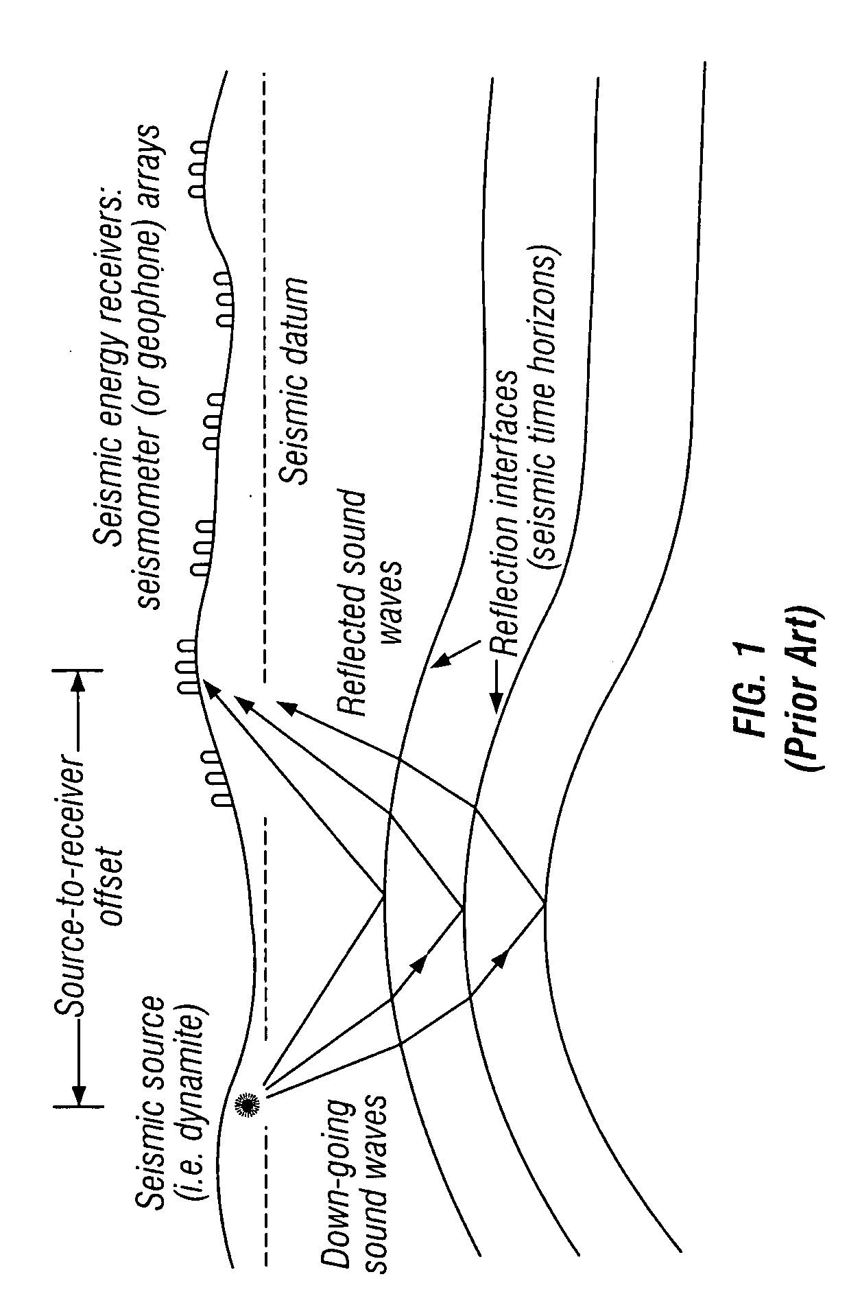
As those of ordinary skill in the pertinent arts will appreciate, both lateral and vertical variations in the velocity of sound waves beneath the Earth's surface can result in the creation of an inaccurate structural interpretation of the subsurface when methods emphasizing only time-domain data are employed.
Consequently, accurate predictions of prospective drilling locations and estimated geological formation depths are difficult to achieve.
The method of Campbell has proven to be deficient, however, in that it is fundamentally only a calibration technique wherein an approximate horizon depth value is adjusted so as to be consistent with known depths of existing wells, rather than a method of deriving a geophysically-consistent velocity function model between well locations using interval velocities from both well data and interpreted seismic horizons.
As discussed in the background section of the Campbell patent, for example, it is well known that the use of processing velocities for depth conversion is highly susceptible to cumulative calculation error.
Another deficiency of the Campbell method is that processing velocities are not in fact the true seismic velocities of the Earth, but estimates based on their effectiveness as parameters in the processing of data, the goal being to derive the best possible data images or signal-to-noise characteristics of a seismic reflector set (see, for example, prior art FIG. 1).
Therefore, even after calibration at well locations, there is a great chance of significant computational error and uncertainty as to the actual geological conditions present between wells.
In addition, irregular lateral deviations of processing velocities, which are common, can result in large computational errors in associated depth values.
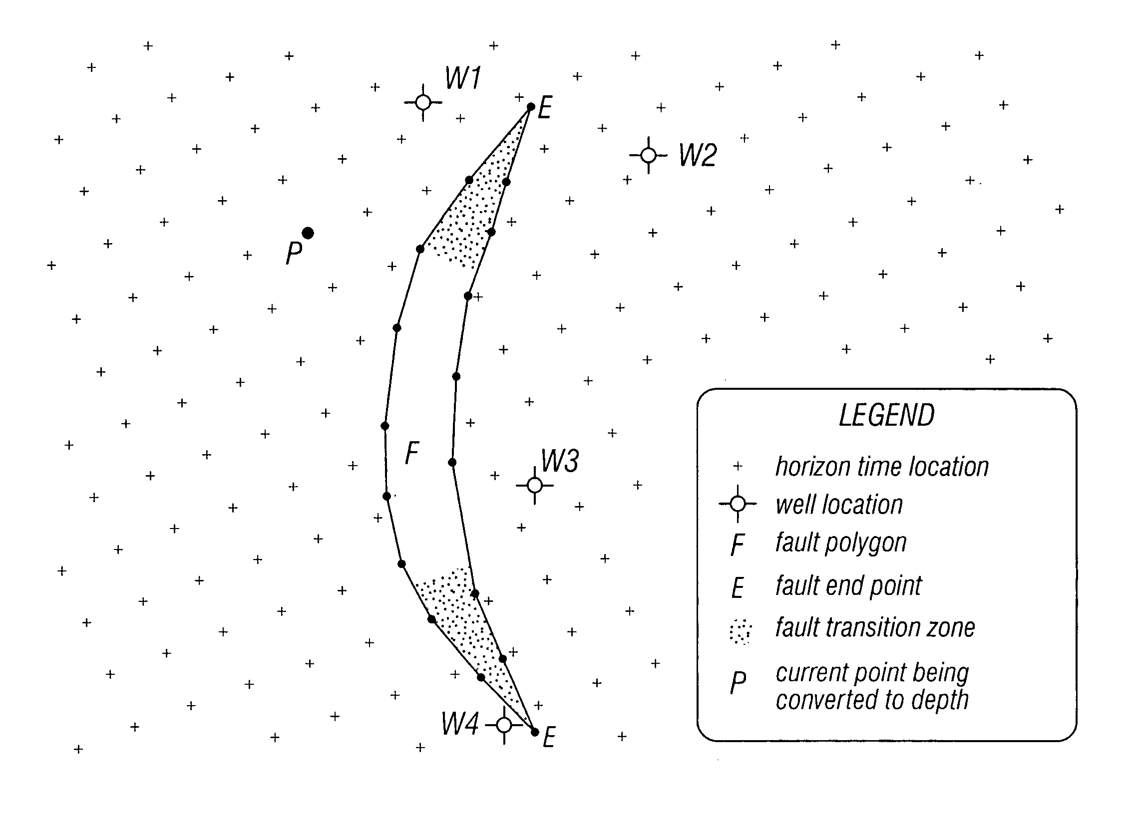
In situations where existing well data is located far away, or where data is derived from wells located on the other side of a fault or are for some other reason unsuitable as a basis for data extrapolation, the method of Campbell is simply inadequate for establishing the relatively precise drilling depth estimates sought by modern geophysicists and drilling investors.
Even though the function is approximately linear, however, the data points do not lie exactly on the extracted line and therefore exact well ties will not result without additional calibration.
More importantly, in instances where the interval velocity is not a linear function with respect to depth, which is the case for the second layer in their article, Keho and Samsu conclude this method is inadequate for estimating accurate drilling depth values.
This method, however, also has pitfalls as velocity logs are not always readily available, and it also requires considerable effort by the interpreter to derive the functions, map the parameters, and hopefully estimate the reliability of the values.
Such an assumption, however, is often incorrect.
For example, lithological changes that have occurred slowly over a great deal of geologic time, lateral and / or vertical changes in the composition of the sedimentary layer, and an inadequate number of horizons used to define layers with different velocity functions can all invalidate the linear model assumption.
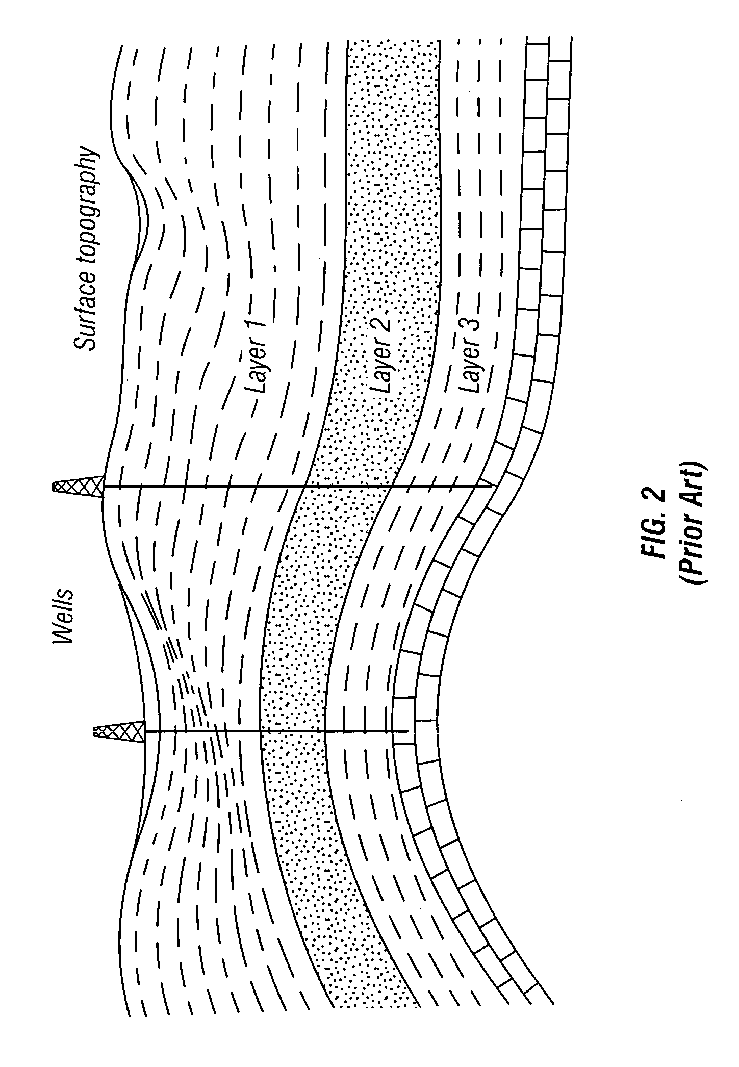
Moreover, in the case of geological mapping, exact well ties and determinations regarding the precise location and extent of faults are particularly problematic when gridded data is used.
In addition, faults can cause abrupt changes to geological formation structure, and bin intervals must be small enough to adequately sample such changes.
As a result, precise computations around fault planes are necessarily compromised, especially when several finely spaced horizon time picks are averaged into one value for a grid bin disposed next to a fault plane.
When applied to depth conversions, estimates using only gridding processes to determine the location of geological formations will incorporate error factors that are simply unacceptable to modern geophysicists and drilling investors.
In certain applications, three-dimensional sampling is also employed, which can create such a massive data volume that an extremely large amount of random-access memory is required, even though the problems associated with faulting and non-exact well ties are not significantly reduced.
In short, even if a geophysically consistent solution of the velocity model between well locations could be determined, conventional gridding processes simply do not provide adequate precision as to allow an accurate conversion of horizon time data into depth values.

Method used


Image

  • Method of estimating geological formation depths by converting interpreted seismic horizons from the time domain to the depth domain
  • Method of estimating geological formation depths by converting interpreted seismic horizons from the time domain to the depth domain
  • Method of estimating geological formation depths by converting interpreted seismic horizons from the time domain to the depth domain

Examples


Embodiment Construction

[0031] Referring again for a moment to prior art FIG. 2, one embodiment of the invention assumes an Earth model in which the subsurface comprises a single, albeit complex, geological layer disposed between the Earth's surface and a relevant seismic horizon. In other embodiments, the accuracy of the disclosed data conversion method is improved for successive seismic horizons by assuming that the Earth's subsurface is not a single layer, but rather a series of layers, wherein horizon data relating to the shallowest horizon is first converted from time to depth, and the resulting depth data is then factored into subsequent conversion of data for the deeper horizons.

[0032] One of the techniques employed in the method of horizon depth conversion disclosed herein is the computation of successive interval velocities for each geological layer. As referred to in the instant disclosure, therefore, the term “geological layers” refers to layers of the Earth's subsurface that are disposed betwe...


PUM


Abstract

According to one aspect of the invention, a method of estimating geological location depths by converting horizon data from the time domain to the depth domain is provided, wherein the method comprises at least a data accumulation step and a data evaluation step, wherein the data evaluation step further comprises assignment of greater statistical weight to data derived from closer data acquisition points than to data derived from further data acquisition points using a weighted regression analysis, with distance being one of several weighting criteria. According to a further aspect of the invention, a method of estimating geological location depths is provided, wherein the method comprises a continuous, layer-by-layer computation of geological formation depths achieved by extracting values from horizon time data set at an exact geographic location of the next deeper horizon, thereby allowing interval computations to be carried out without the need for gridding. According to a still further aspect of the invention, a method of estimating geological formation depths is provided, wherein the method comprises estimating an expected error based on data scatter, and then allowing an alternative solution to be either partially or fully employed in areas where the accumulated data is insufficient to determine an acceptably reliable geophysical model.

Description

[0001] FIELD OF THE INVENTION [0002] The present invention relates generally to methods of estimating geological formation depths using interpreted seismic horizon data, and, in a particular, non-limiting embodiment, to a method of estimating geological formation depths by converting interpreted seismic horizon data from the time domain to the depth domain. BACKGROUND OF THE INVENTION [0003] Conventional interpretation of two-dimensional and three-dimensional seismic data typically results in a converted data set representing the two-way seismic travel time of energy waves reflected by geological deposits formed beneath the Earth's surface. Data representing specific geological formations are called seismic horizons, and are oftentimes named after the formation or type of geological layer being represented. [0004] In the past decade, horizon data has usually been created by a seismic interpreter using a computer or processor of some type and an industry-specific software package. At...

Claims


Application Information

Patent Timeline
Patent Type & Authority Applications(United States)
IPC IPC(8): G01V9/00
CPCG01V1/32G01V1/30
Inventor ADAMS, STEVEN L.
Owner ADAMS STEVEN L
Why Eureka
Try Eureka