
Strengthening device to increase strength of grout layer

a strengthening device and grout layer technology, applied in snow traps, hose connections, building repairs, etc., can solve the problems of cracks or failures on the grout layer caused by excessive bearing stress along the edge or the corner of the grout layer, and the strength of the edge against the moment load is relatively weaker than that against the vertical load,

Inactive Publication Date: 2006-03-09
RES INST OF IND SCI & TECH
View PDF12 Cites 35 Cited by
  • Summary
  • Abstract
  • Description
  • Claims
  • Application Information

AI Technical Summary

Benefits of technology

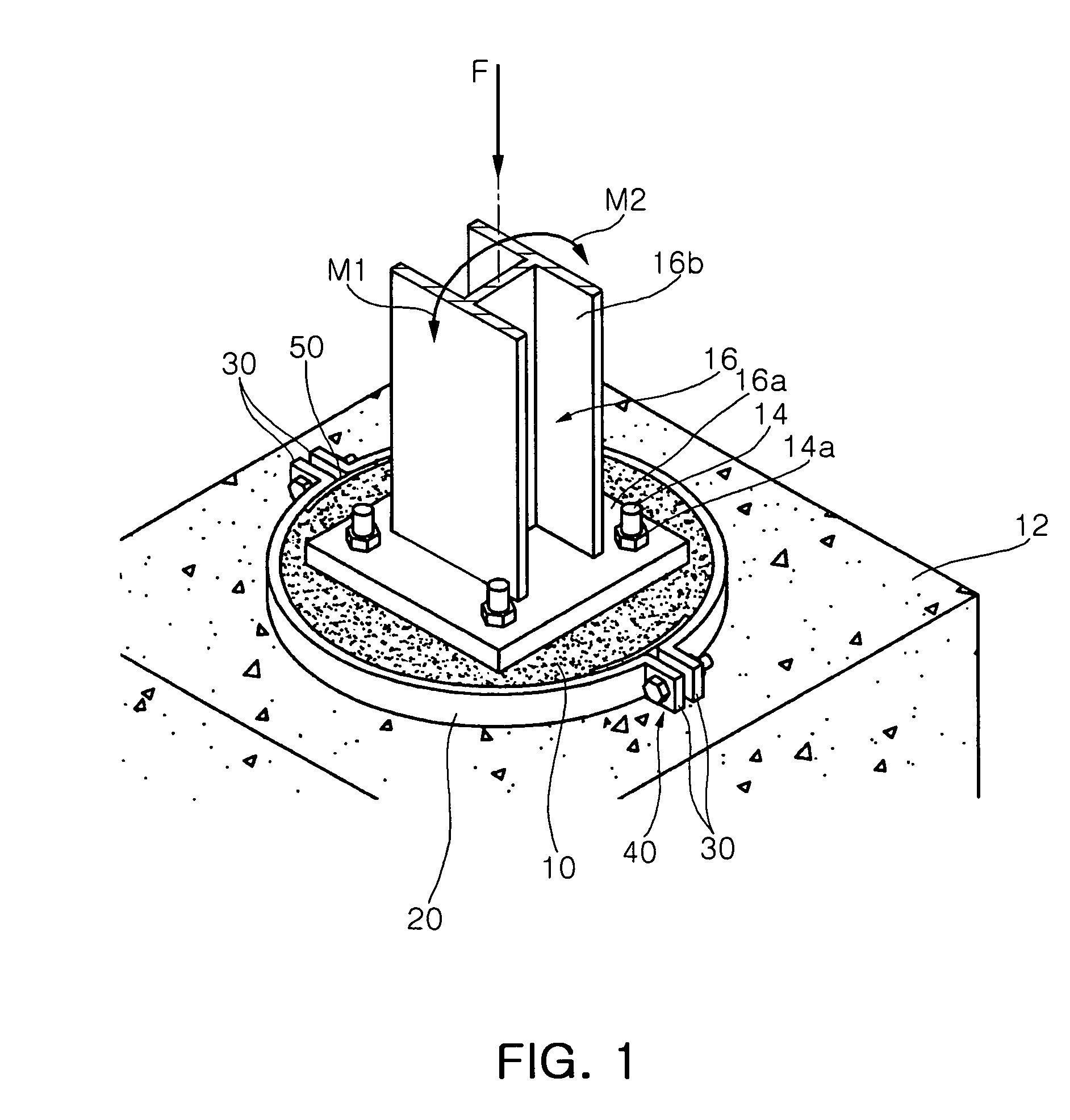
[0016] An object of the present invention is to provide a strengthening device to increase the strength of a grout layer, which improves a structural safety of an upper structure by effectively preventing or minimizing a failure of the grout layer due to vertical load and moment load transferred from the upper structure, such as a column member or a bridge bearing.
[0018] To achieve these objects and other advantages and in accordance with the purpose of the invention, as embodied and broadly described herein, there is provided a strengthening device to increase the strength of a grout layer, which includes: clamp members interconnected and clamped to surround a grout layer on a concrete base on which an upper structure is installed, so as to increase the strength of the grout layer; connection members provided to edges of the clamp members to connect the clamp members; and fastening means fastened between the connection members in order to enable the clamp members to clamp the grout layer.
[0024] Meanwhile, the strengthening device may further include grout blocking members provided between the connection members and the grout layer so as to prevent grout from leaking out through a gap between the connection members.

Problems solved by technology

However, since an edge of the grout layer has no restraining force applied inward from the outline, the strength of the edge against the moment load is relatively weaker than that against the vertical load.
The excessive bearing stress generated along the edge or the corner of the grout layer becomes a fatal factor of crack or failure on the grout layer unless a restraining force is applied inward (or, toward a center) from an outline of the grout layer.
As a result, moment loads repeatedly applied to the upper structure such as a column member may break down the grout layer easily.
In addition, this phenomenon makes it difficult that loads transferred from the upper structure is distributed to the concrete base, resulting in deteriorated structural safety of the grout layer as well as the upper structure such as a column member or a bridge bearing installed thereon.

Method used


Image

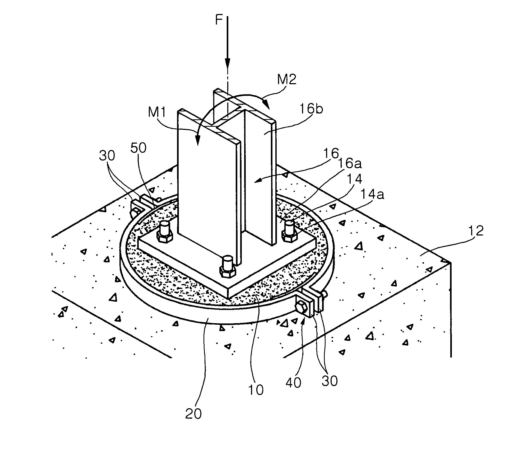
  • Strengthening device to increase strength of grout layer
  • Strengthening device to increase strength of grout layer
  • Strengthening device to increase strength of grout layer

Examples


first embodiment

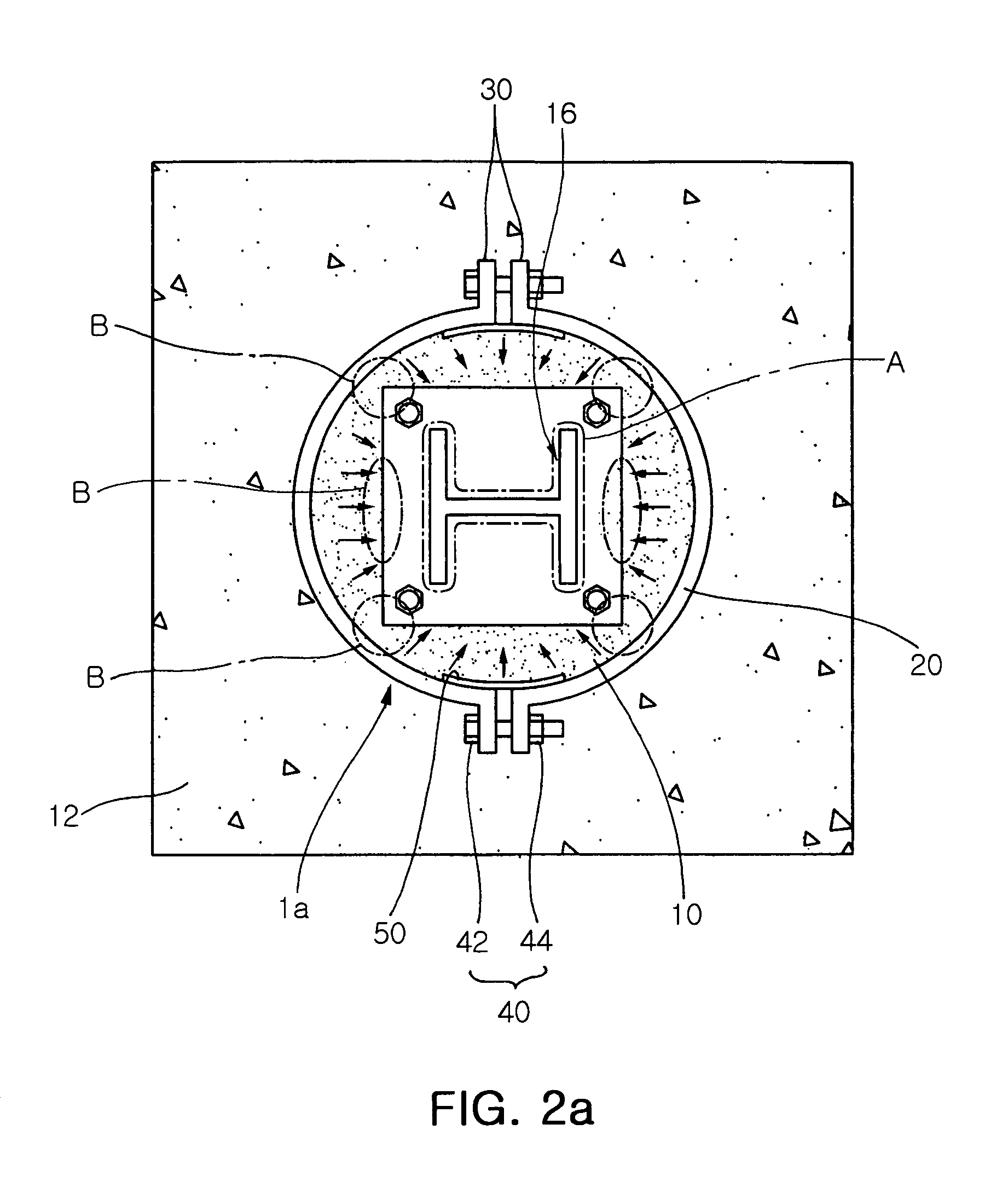
[0057] Meanwhile, as shown in FIG. 2a, the strengthening device 1a to increase the strength of a grout layer configures a circular looped section by means of clamp members 20 assembled into a circular shape. Thus, hoop tension in the clamp members 20 applies regular clamping force (or, restraining force), expressed by arrows, to the grout layer. Thus, this strengthening device 1a is most preferable to increase a bearing strength.

[0058] In addition, the strengthening device 1b to increase the strength of a grout layer according to the second embodiment of the present invention configures a quadrangular looped section as shown in FIG. 2b. At this time, a restraining force (see arrows in FIG. 2b) applied to the grout layer by the strengthening device 1b is less regular as a whole than that by the strengthening device 1a of the first embodiment. Thus, the strengthening device 1b of the second embodiment is not so efficient to increase a bearing strength of the grout layer. However, con...

second embodiment

[0085] In addition, the grout blocking member 50 of a plate shape as shown in FIGS. 3a and 3b and the grout blocking member 50 provided with the hook 52 as shown in FIG. 4 may be applied to the second embodiment and its modifications as they are.

[0086]FIG. 5a is a perspective view showing that the strengthening device 1b to increase the strength of a grout layer according to the second embodiment of the present invention as shown in FIG. 2b is actually used.

[0087] At this time, as shown in FIG. 5a, the strengthening device 1b of the second embodiment includes the clamp members 20, the connection members 30, the fastening means 40 and the grout blocking members 50 identically to the strengthening device 1a of the first embodiment, but the clamp members 20 configure a quadrangular looped section.

[0088] Thus, the strengthening device 1b of the second embodiment may be used for increasing the strength of the grout layer 10 while minimizing a space for an upper structure in case that t...

third embodiment

[0099] Thus, as shown in FIG. 7b, the grout layer leveling means 60 enables to check whether a horizontal leveled state of the grout layer 10 is constant, in case that the strengthening device of the present invention is positioned on the concrete base 12, a mold is provided by connecting the connection members 30 by means of the fastening means 40, and then grout is placed therein to form the grout layer 10.

[0100] Resultantly, the grout layer leveling means 60 of the present invention makes it possible to keep a horizontal level of the grout level constantly with using the strengthening device as a mold when grout is placed, thereby allowing easy construction of the grout layer 10.

[0101] Of course, when the strengthening device provided with the grout layer leveling means 60 is used, it should be assumed that the surface of the concrete base on which the grout layer is formed is already leveled.

[0102] At this time, as shown in FIG. 7b, the height of the clamp member 20 should be ...


PUM


Abstract

Provided is a strengthening device to increase the strength of a grout layer. In the strengthening device, clamp members are interconnected and clamped to surround a grout layer on a concrete base, on which an upper structure is installed, so as to increase the strength of the grout layer. Connection members are provided to edges of the clamp members to connect the clamp members. Fastening means is fastened between the connection members in order to enable the clamp members to clamp the grout layer. This strengthening device acts as a mold to facilitate easy construction when grout is placed, and surrounds the grout layer to increase the strength of the grout layer after grout is cured, thereby effectively preventing and minimizing failure of the grout layer caused by loads transferred from an upper structure such as a column member or a bridge bearing.

Description

RELATED APPLICATION [0001] The present application is based on, and claims priority from, Korean Application Number 2004-70810 filed Sep. 6, 2004, and Korean Application Number 2005-49904 filed Jun. 10, 2005, the disclosure of which is hereby incorporated by reference herein in its entirety. BACKGROUND OF THE INVENTION [0002] 1. Field of the Invention [0003] The present invention relates to a strengthening device to increase the strength of a grout layer, placed on a concrete base for keeping a structural safety of an upper structure, and more particularly to a strengthening device to increase the strength of a grout layer, which improves a structural safety of an upper structure by fastening the grout layer placed on a concrete base to give a restraining force thereto so that a failure of the grout layer due to loads transferred from the upper structure such as a column member or a bridge bearing installed on the grout layer may be prevented or minimized. [0004] 2. Description of t...

Claims


Application Information

Patent Timeline
IPC IPC(8): E02D27/00
CPCE02D27/00Y10T24/1459Y10T24/1443E02D27/42
Inventor LEE, DAE YONG
Owner RES INST OF IND SCI & TECH
Learn More