Inflatable member projectile

a technology of projectiles and members, applied in the field of inflatable member projectiles, can solve problems such as difficulties experienced

Inactive Publication Date: 2006-03-09
KILVERT ANTHONY DAVID
View PDF0 Cites 7 Cited by
  • Summary
  • Abstract
  • Description
  • Claims
  • Application Information

AI Technical Summary

Benefits of technology

[0021] Conveniently, the cradle comprises a number of radiating channels, each locating one inflatable roll. Whilst each of the latter is actually rolled, it conveniently has a serpentine portion in the bottom of its channel, for assisting in lifting the roll over a closed end of the channel, a joint line between the cradle and the nose cone being at an even height along the channels and across the closed end. Alternatively, the ends of the channels can be open on deployment and closed by webs on the nose cone prior to deployment.

Problems solved by technology

Difficulties have been experienced in deploying the inflatable member to extend the wire over a sufficient area of the sea and sufficiently quickly to form an effective deterrent.

Method used


Image

  • Inflatable member projectile
  • Inflatable member projectile
  • Inflatable member projectile

Examples


Embodiment Construction

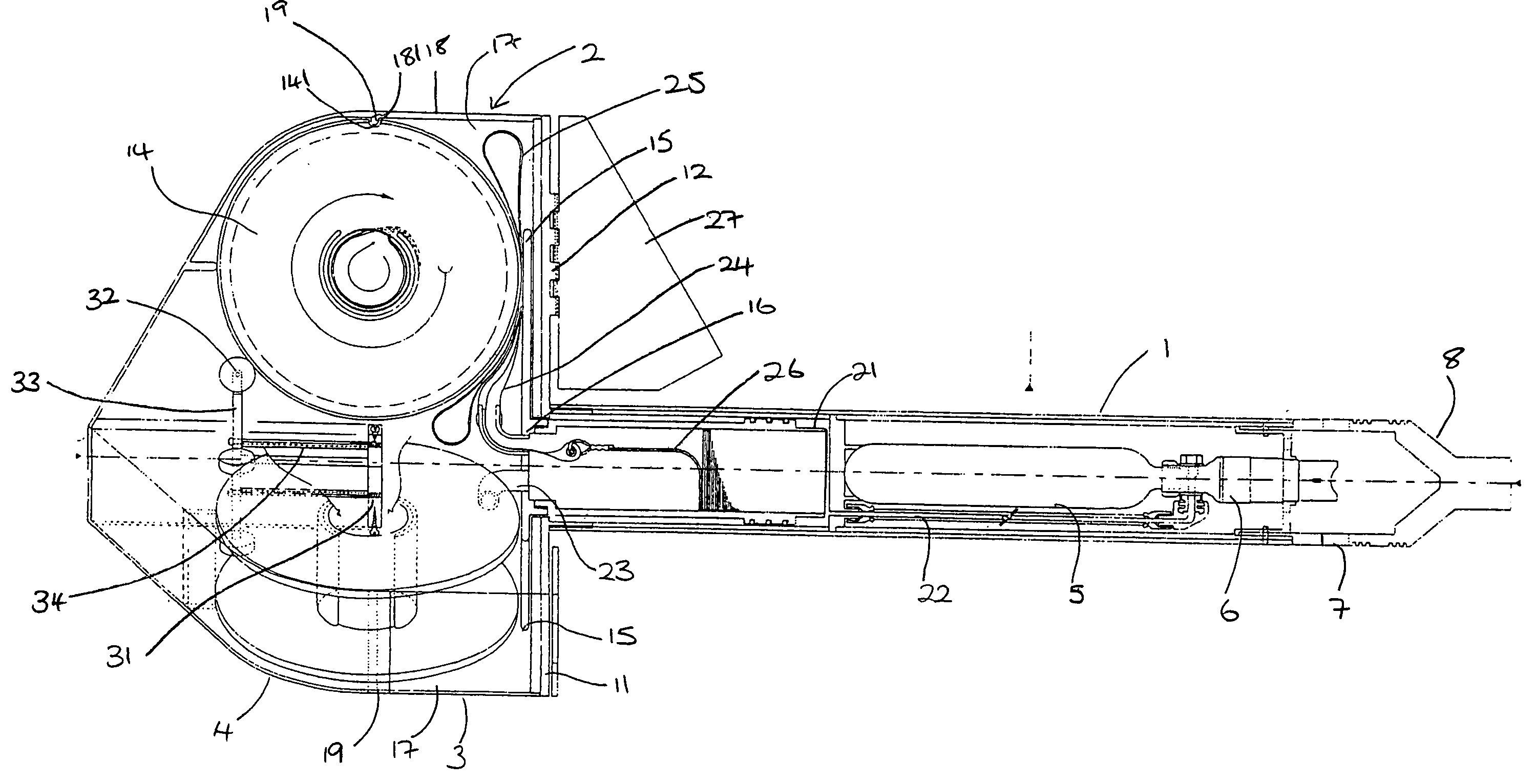
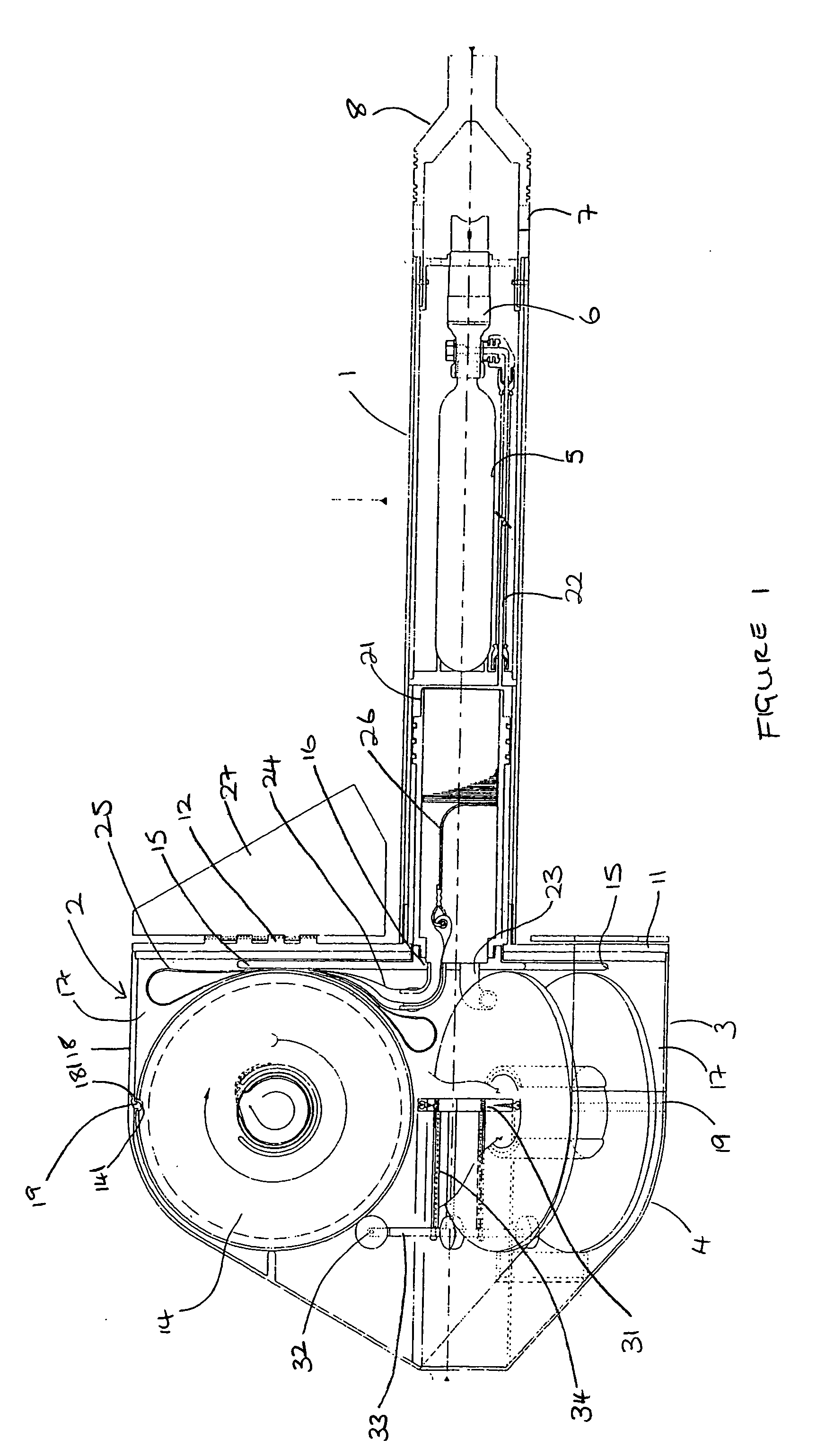
[0026] Referring to the drawings, the projectile comprises a body 1 with a nose cone 2 comprised of a roll cradle 3 and a cap 4. The body houses an inflation gas bottle 5 with a release mechanism 6, to which water has access via openings 7. On launching of the projectile, the nose cone which has air filled voids floats, whilst the tail end 8 sinks, allowing water in and releasing gas, as described in more detail below.

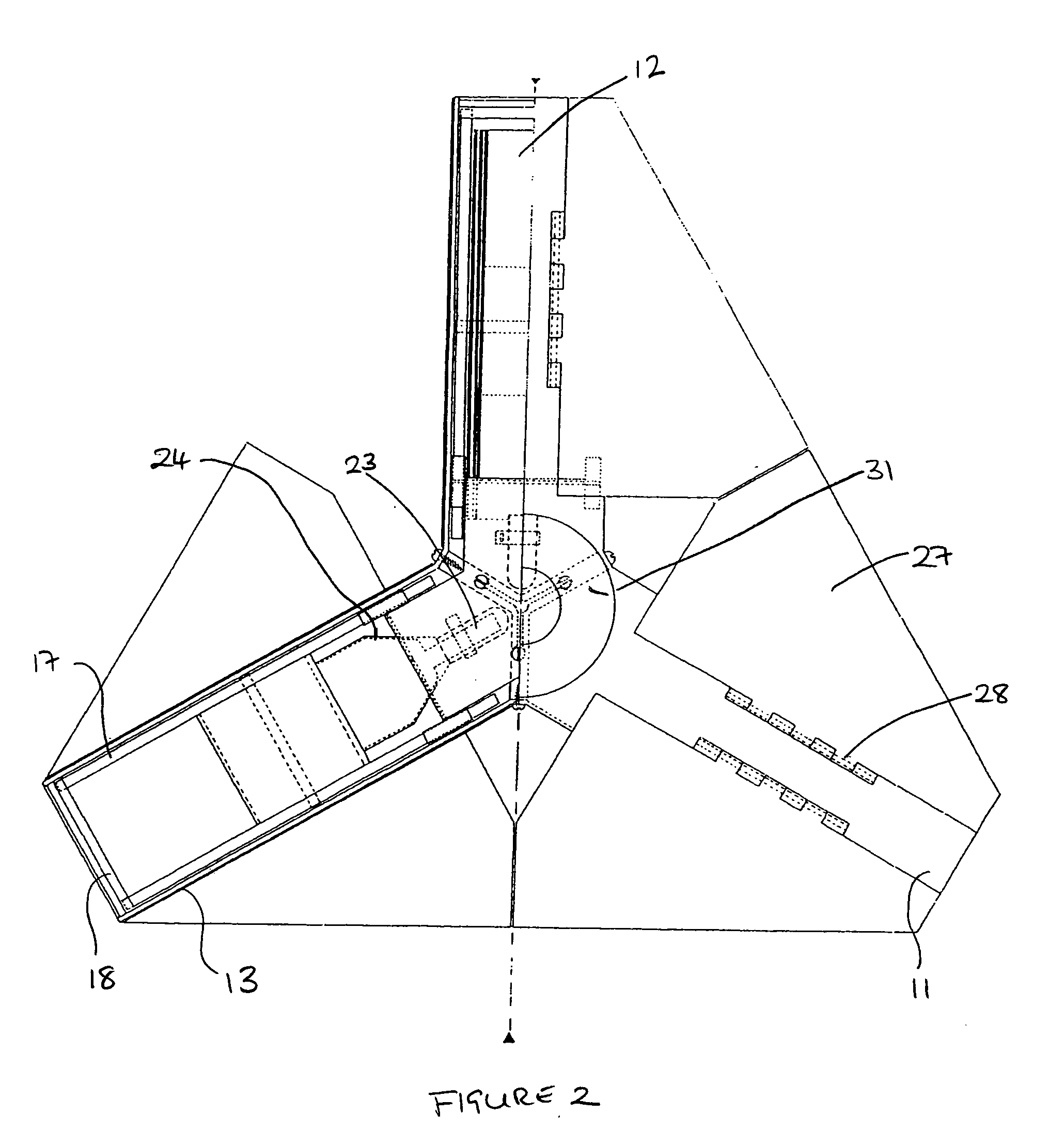
[0027] The cradle 3 has three arms 11,12,13. The arms are channels, opening into each other centrally, where a three armed brace 31 holds the free edges of the channels together. Each channel supports a roll of inflatable tubing 14, equipped with stiffening and fouling elements, as described in the Second International Application. The rolls rest on the three fingers 15 of an ejector having a hub 16 and arranged in the channels beneath the brace 31. The cradle itself is fast with the body, having channel sides 17 and ends 18 retaining the rolls. The cap is of compleme...


PUM


Abstract

An inflatable member projectile comprising: a projectile body having one end more buoyant than the other; an inflatable roll for vessel-immobilising; an inflation gas bottle at the less buoyant end of the body for inflating the inflatable roll and a cradle for supporting the roll in an orientation such that the inflatable roll unrolls in a generally pre-determined deployment direction, i.e. with the projectile floating with the less buoyant end down corresponding with their orientation. The cradle comprises a number of radiating channels, each locating one inflatable roll. Each roll has a serpentine portion in the bottom of its channel, for assisting in lifting the roll over a closed end of the channel. The cradle has a lifter for lifting the rolls up out of the cradle, actuated by the inflation gas.

Description

CROSS-REFERENCE TO RELATED APPLICATIONS [0001] The present application claims priority under 35 USC § 119 to United Kingdom Patent Application No. 0318500.6 filed on Aug. 7, 2003. TECHNICAL FIELD [0002] The present invention relates to an inflatable member projectile, particularly though not exclusively for use as a vessel immobiliser projectile. BACKGROUND OF THE INVENTION [0003] It is known to project a wire into the path of a vessel, to immobilise the vessel by fouling its propeller, as in a pirate attack. [0004] In earlier International Patent Application No WO 99 / 30966 (hereinafter the “First International Application”), there was proposed: [0005] An immobiliser device for a sea-faring vessel having a housing in which is stowed, in an unextended state, a length of fouling wire which, in use, is designed to foul the propeller and / or motor of a target vessel. The wire is automatically ejected from the housing on or soon after contact with the water. The wire may be ejected by bei...

Claims


Application Information

Patent Timeline
Patent Type & Authority Applications(United States)
IPC IPC(8): B64D1/04F42B22/00B63C9/08B63C9/26F41B15/00F41H11/05F41H13/00F42B12/36
CPCB63C9/08B63C9/24B63C9/26F41H13/00F41B15/00F41H11/05B63C2009/0035
Inventor KILVERT, ANTHONY DAVID
Owner KILVERT ANTHONY DAVID
Why Eureka
Try Eureka