Filling device for an anesthetic evaporator

a technology of anesthetic evaporator and filling device, which is applied in the direction of respirator, liquid handling, packaging goods type, etc., can solve the problems of residual volume and end of filling operation, and achieve the effect of increasing the capacity of the anesthetic tank

Active Publication Date: 2006-03-09
DRAGERWERK AG
View PDF6 Cites 13 Cited by
  • Summary
  • Abstract
  • Description
  • Claims
  • Application Information

AI Technical Summary

Benefits of technology

[0009] The advantage of the present invention is essentially that a vent hole, which is opened immediately after the termination of the filling operation in order to enable excess anesthetic to flow off into the anesthetic tank from the filling device, is arranged above a fluid channel, via which the anesthetic tank is filled with anesthetic. The capacity of the anesthetic tank is increased by the vent hole, so that a residual volume of anesthetic, which has remained in the filling device, can still be taken up.
[0010] The anesthetic bottle and the anesthetic tank are connected with one another in the form of communicating vessels during the filling operation. The gas and liquid exchange between the anesthetic bottle and the anesthetic tank takes place via the fluid channel at the filling device. The liquid level in the anesthetic tank rises to the level of the fluid channel. The filling operation is then terminated automatically, because no exchange of gas is possible any longer through the fluid channel. When the user removes the anesthetic bottle from the filling device to the extent that the bottle valve of the anesthetic bottle is just closed, the vent hole is released by a vent valve, so that the residual volume left can flow off from the filling device into the anesthetic tank.
[0011] The vent valve is advantageously mechanically connected with the filling valve such that it is switched into the open position immediately after the filling operation, but it is switched into the closed position during the filling operation. The liquid level in the anesthetic tank can thus rise only up to the level of the fluid channel during the filling operation.
[0012] Provisions are advantageously made for providing as the vent valve a closing bolt that can be displaced telescopically in relation to the valve plate of the filling valve. The closing bolt is pressed during the filling operation against the vent hole and it closes same. The valve plate of the filling valve is connected in this case directly with the outer sleeve of the anesthetic bottle via the pins. When the anesthetic bottle is pushed completely into the mounting hole of the filling device and the bottle valve opens, the valve plate reaches the end stop and the closing bolt is in contact by its flat packing with the vent hole. When the anesthetic bottle is pulled somewhat out of the filling device after the filling, the position of the valve plate changes as well, and the pressing force exerted by the closing bolt on the vent hole decreases until the vent hole is finally opened. The bottle valve will have already closed by that point in time, so that excess anesthetic can still be taken up from the filling device in the anesthetic tank. The valve plate, which is rigidly coupled with the outer sleeve of the anesthetic bottle, is used to release the vent hole via the closing bolt when the bottle valve of the anesthetic bottle has just closed.
[0013] An exemplary embodiment of the present invention is shown in the drawings and will be explained in greater detail below. The various features of novelty which characterize the invention are pointed out with particularity in the claims annexed to and forming a part of this disclosure. For a better understanding of the invention, its operating advantages and specific objects attained by its uses, reference is made to the accompanying drawings and descriptive matter in which the preferred embodiment of the invention is illustrated.

Problems solved by technology

When the anesthetic tank is filled with anesthetic to the maximum filling level, the filling operation ends due to the closure of the fluid channel, because no liquid or gas exchange is possible any longer between the anesthetic bottle and the anesthetic tank.
Such residual volumes are problematic especially in case of anesthetics with low boiling points, because they escape directly into the environment after the removal of the anesthetic bottle from the filling device.

Method used


Image

  • Filling device for an anesthetic evaporator
  • Filling device for an anesthetic evaporator
  • Filling device for an anesthetic evaporator

Examples


Embodiment Construction

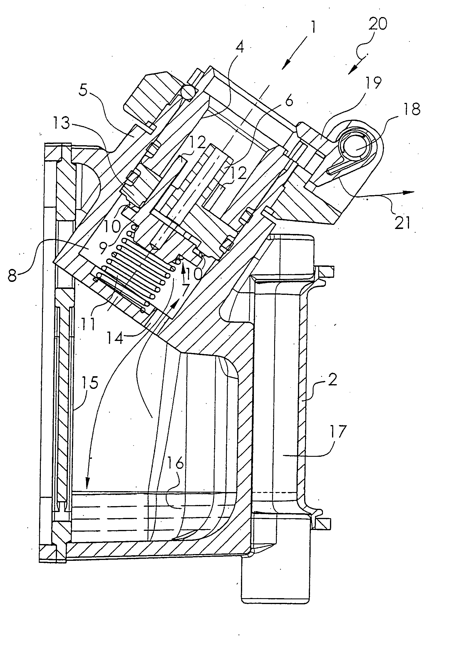
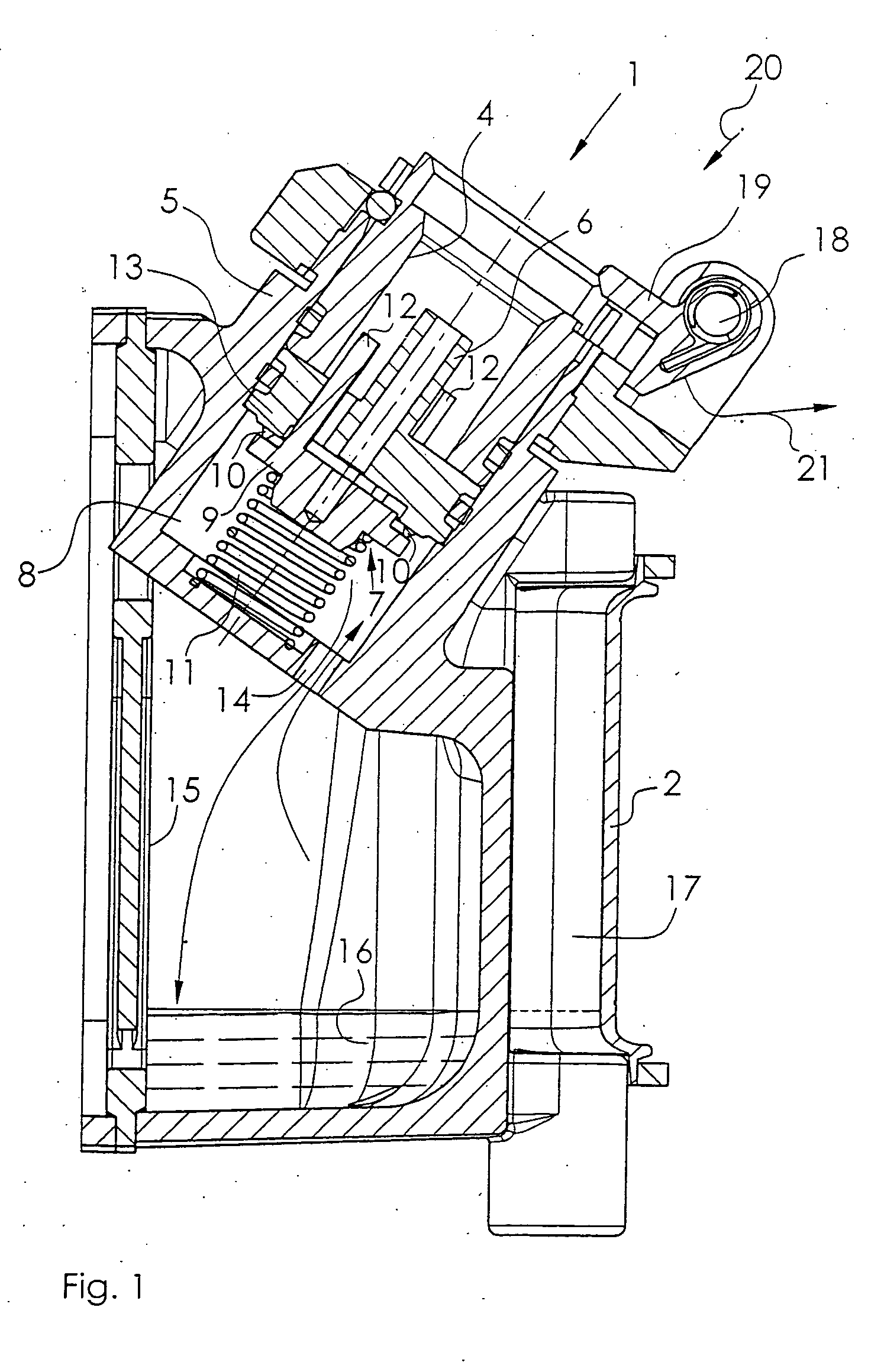
[0020] Referring to the drawings in particular, FIG. 1 schematically illustrates a filling device 1 according to the state of the art at an anesthetic evaporator 2, which is not shown more explicitly. The filling device 1 comprises a mounting hole 4 with a tubular inner part 6 fixed in a valve housing 5. A filling valve 7, which is arranged in a valve chamber 8 under the inner part 6, contains a valve plate 9, a sealing crater 10 and a valve spring 11, which presses the valve plate 9 against the sealing crater 10. Three pins 12 connected rigidly with the valve plate 9 pass through a mounting plate 13 of the inner part 6 and into the mounting hole 4. The valve chamber 8 is connected via a fluid channel 14 with an anesthetic tank 15 for receiving liquid anesthetic 16. The filling level of the anesthetic 16 in the anesthetic tank 15 can be read on a viewing glass 17. A bar 19, which is pivotable around a bolt 18, is pretensioned with a spring and is displaceable along the arrows 20, 21...


PUM

PropertyMeasurementUnit
volumeaaaaaaaaaa
liquidaaaaaaaaaa
boiling pointsaaaaaaaaaa

Abstract

A filling device for an anesthetic evaporator has filling of an anesthetic evaporator is possible. To accomplish the object, an additional vent hole (36), which is opened immediately after the filling in order for excess anesthetic volume to be able to flow out of the filling device into the anesthetic tank (15) of the anesthetic evaporator (2), is provided within the filling device above a fluid channel (14), via which both the gas and liquid exchange takes place during the filling.

Description

CROSS REFERENCE TO RELATED APPLICATIONS [0001] This application claims the benefit of priority under 35 U.S.C. § 119 of German Application DE 10 2004 043 652.5 filed Sep. 9, 2004, the entire contents of which are incorporated herein by reference. FIELD OF THE INVENTION [0002] The present invention pertains to an anesthetic evaporator. BACKGROUND OF THE INVENTION [0003] A filling device of this type has become known from WO 96 / 06301. An anesthetic bottle is provided with a stationary outer tube and an inner tube, which is displaceable in such a way that it can perform a lifting motion and with which a bottle valve on the anesthetic bottle can be opened. A filling device at the anesthetic evaporator has a mounting hole for the outer tube and a stationary inner part, which can be brought into functional connection with the inner tube of the anesthetic bottle. A filling valve of the filling device, which valve is in connection with an anesthetic tank, has a valve plate, which can be lif...

Claims


Application Information

Patent Timeline
Patent Type & Authority Applications(United States)
IPC IPC(8): B65B3/04A61M16/18
CPCA61M16/183
Inventor BUNKE, CLAUSWITT, MATTHIASKUNZ, RAINERMULLER, JURGENHEYER, SVENREICHERT, DIRK
Owner DRAGERWERK AG
Why Eureka
Try Eureka