Shape memory alloy for erosion control of downhole tools

Inactive Publication Date: 2006-03-09
HALLIBURTON ENERGY SERVICES INC
View PDF28 Cites 93 Cited by
  • Summary
  • Abstract
  • Description
  • Claims
  • Application Information

AI Technical Summary

Benefits of technology

[0016] In a further aspect, the present invention is directed to a method for minimizing erosion in a component. The method includes the steps of disposing the component, which includes a shape memory alloy integrated with a surface of the component, and exposing the shape memo

Problems solved by technology

It has been found, however, that even when using spherical sealing surfaces leakage may occur.
Specifically, erosion of the concave va

Method used


Image

  • Shape memory alloy for erosion control of downhole tools
  • Shape memory alloy for erosion control of downhole tools
  • Shape memory alloy for erosion control of downhole tools

Examples


Example

[0026] While the making and using of various embodiments of the present invention are discussed in detail below, it should be appreciated that the present invention provides many applicable inventive concepts which can be embodied in a wide variety of specific contexts. The specific embodiments discussed herein are merely illustrative of specific ways to make and use the invention and do not delimit the scope of the present invention.

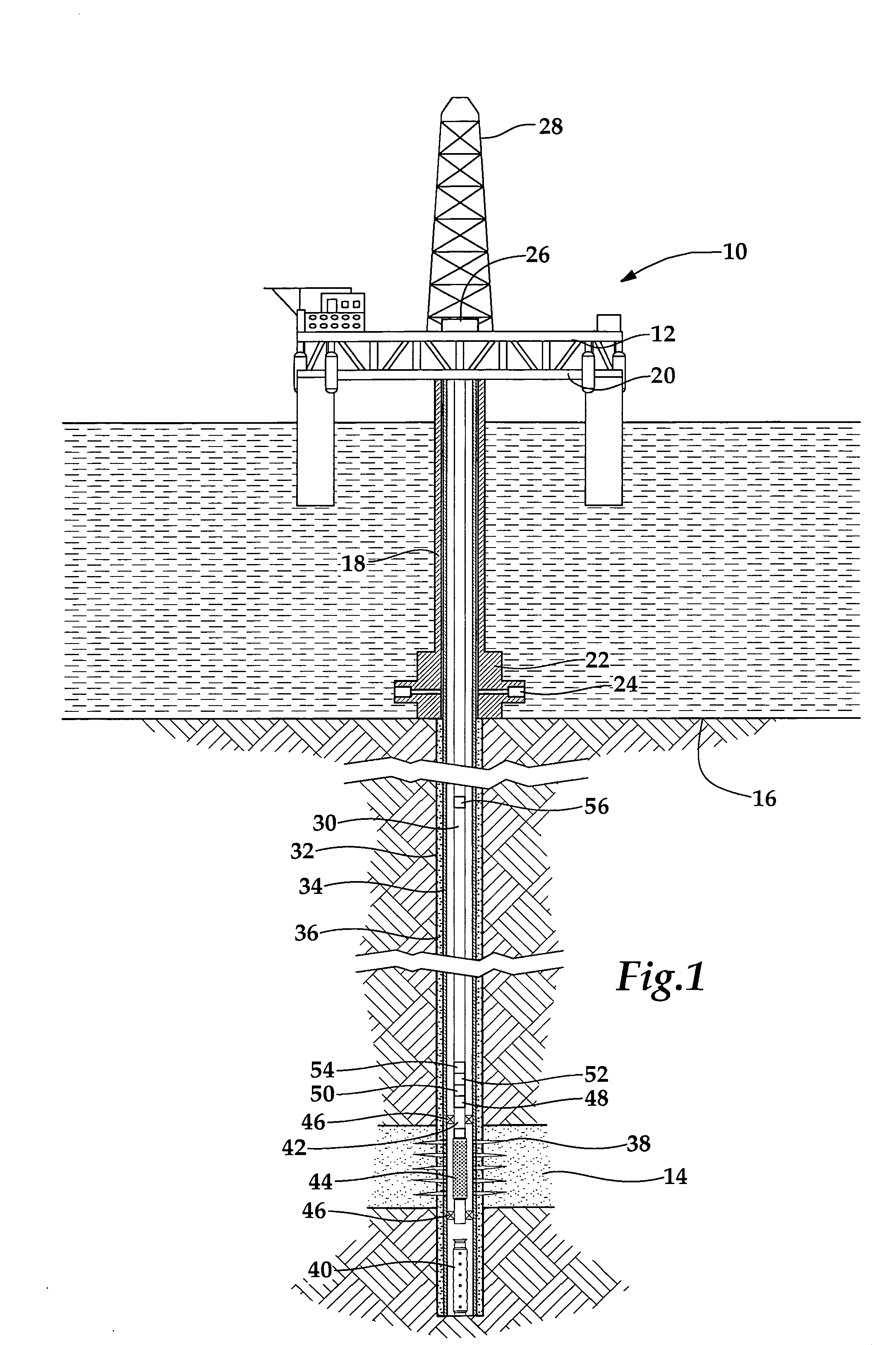
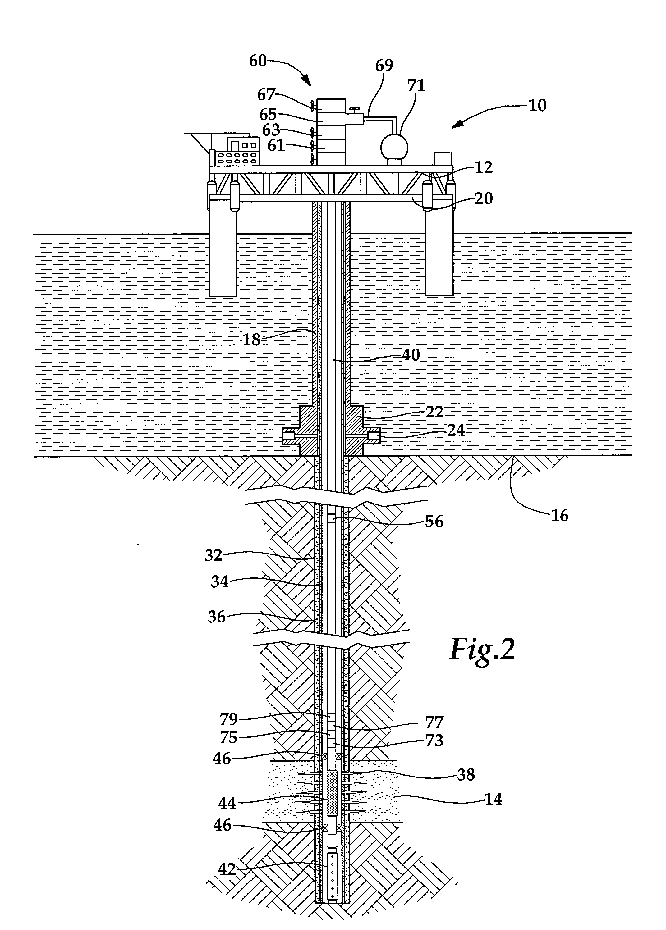
[0027] Referring initially to FIG. 1, an offshore oil and gas platform performing completion operations is schematically illustrated and generally designated 10. A semi-submersible platform 12 is centered over a submerged oil and gas formation 14 located below sea floor 16. A subsea conduit 18 extends from deck 20 of platform 12 to wellhead installation 22 including blowout preventers 24. Platform 12 has a hoisting apparatus 26 and a derrick 28 for raising and lowering pipe strings such as completion string 30.

[0028] A wellbore 32 extends through the ...


PUM


Abstract

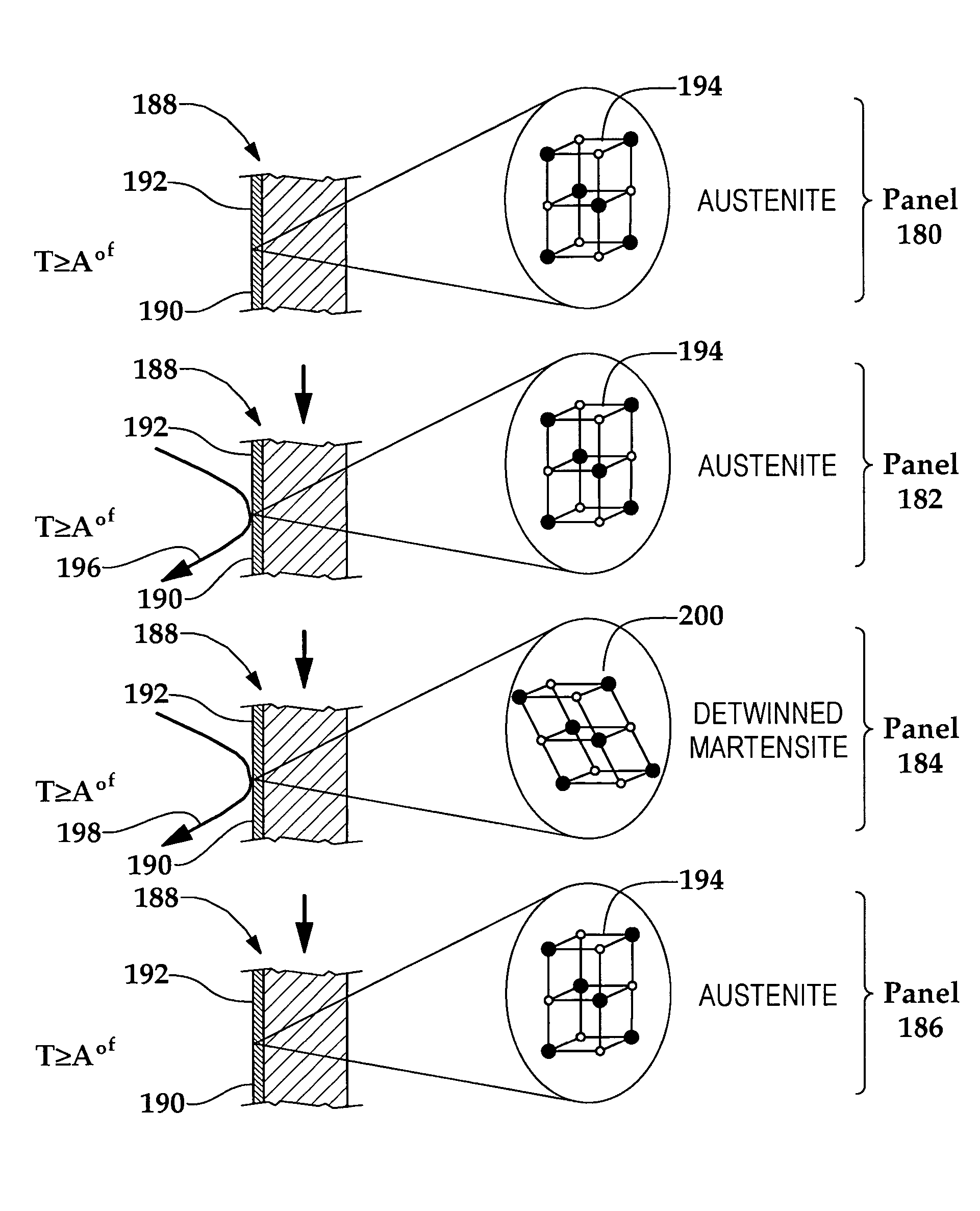
A downhole fluid flow control device (188) and method for minimizing erosion are disclosed. The downhole fluid flow control device (188) includes a downhole surface (190) subjectable to an erosive stress (196, 198) which may be a moving fluid or an erosive agent, for example. A shape memory alloy (192) is integrated with the downhole surface (190) in order to provide erosion resistance by reversibly transforming from an austenitic phase (194) to a martensitic phase (200) in response to the application of the erosive stress (196, 198). Further, the shape memory alloy (192) reversibly transforms from the martensitic phase (200) to the austenitic phase (192) in response to the presence of sufficient heat.

Description

TECHNICAL FIELD OF THE INVENTION [0001] The present invention relates, in general, to preventing erosion of downhole tools positioned within a wellbore that traverses a subterranean hydrocarbon bearing formation and, in particular, to downhole tools having a shape memory alloy integrated therein to provide erosion resistance. BACKGROUND OF THE INVENTION [0002] Without limiting the scope of the invention, the background will describe surface controlled, subsurface safety valves, as an example. [0003] Surface controlled, subsurface safety valves are commonly used to shut in oil and gas wells in the event of a failure or hazardous condition at the well surface. Such safety valves are typically fitted into the production tubing and operate to block the flow of formation fluid upwardly therethrough. The subsurface safety valve provides automatic shutoff of production flow in response to a variety of out of range safety conditions that can be sensed or indicated at the surface. For exampl...

Claims


Application Information

Patent Timeline
IPC IPC(8): E21B34/00
CPCE21B43/12E21B34/066
Inventor FRIPP, MICHAEL L.HAMID, SYEDSCHULTZ, ROGER L.DAGENAIS, PETE C.MICHAEL, ROBERT KENSKINNER, NEAL G.
Owner HALLIBURTON ENERGY SERVICES INC
Why Eureka
Try Eureka