
Pipe joint gasket

a gasket and pipe joint technology, applied in the field of gaskets, can solve the problems of increasing the cost of gaskets made of elastomeric materials, increasing the cost of gaskets made of these materials, and plastics are typically less flexible and/or compressible, so as to achieve less construction cost, easy deformation, and increased cost of substantially resilient materials

Inactive Publication Date: 2006-03-09
PRESS SEAL GASKET
View PDF21 Cites 20 Cited by
  • Summary
  • Abstract
  • Description
  • Claims
  • Application Information

AI Technical Summary

Benefits of technology

[0012] The gasket may advantageously be manufactured using a two-shot injection co-molding process. In this method, the material for the main body portion is heated and injected into a mold die. Then, before the substantially rigid material fully cures, the cores in the mold die are moved and a second, substantially resilient material is injected into the die and molded to the substantially rigid material, the substantially resilient material forming the sealing portion of the gasket. This two-shot injection molding process allows the second material to form a firm structural bond with the first material before the first material completely cures.
[0016] Advantageously, the substantially rigid material of the main body portion stiffens the gasket in the gasket region that interfaces with concrete structure, while the substantially resilient material of the sealing portion provides flexibility in the gasket region that seals to the pipe. This design allows the gasket to rigidly hold its shape during the casting process whereas a gasket entirely made of a resilient material could potentially more easily deform from the weight of the wet concrete. Similarly, a gasket made of an entirely resilient material requires a mandrel to maintain the shape of the gasket during the casting process whereas the body portions of the present embodiments may be constructed of a sufficiently rigid material such that a mandrel may not be needed.
[0017] Furthermore, the present gasket, made of both substantially rigid and substantially resilient materials, is less expensive to construct than a gasket entirely made of a substantially resilient material, such as rubber, due to the higher costs of the substantially resilient materials. The anchoring flange of the present embodiments may also be made of the same substantially rigid material as the body portion and thus strengthen the connection between the gasket and the concrete structure to prevent the gasket from becoming dislodged. Further, the relatively resilient portion of the gasket allows the gasket to easily seal to a pipe via a clamped seal or compression seal whereas a gasket entirely made of a rigid material would be less able to conform to the shape and irregularities of a pipe.

Problems solved by technology

Although elastomeric gaskets form robust, effective seals with pipes, a disadvantage of same is that elastomeric materials are typically expensive and therefore increase the cost of gaskets which are made of these materials.
On the other hand, although plastic materials are less expensive, plastics are typically less flexible and / or compressible than elastomeric or rubber materials and may be less suitable for sealing pipes in certain applications.

Method used


Image

  • Pipe joint gasket
  • Pipe joint gasket
  • Pipe joint gasket

Examples


Embodiment Construction

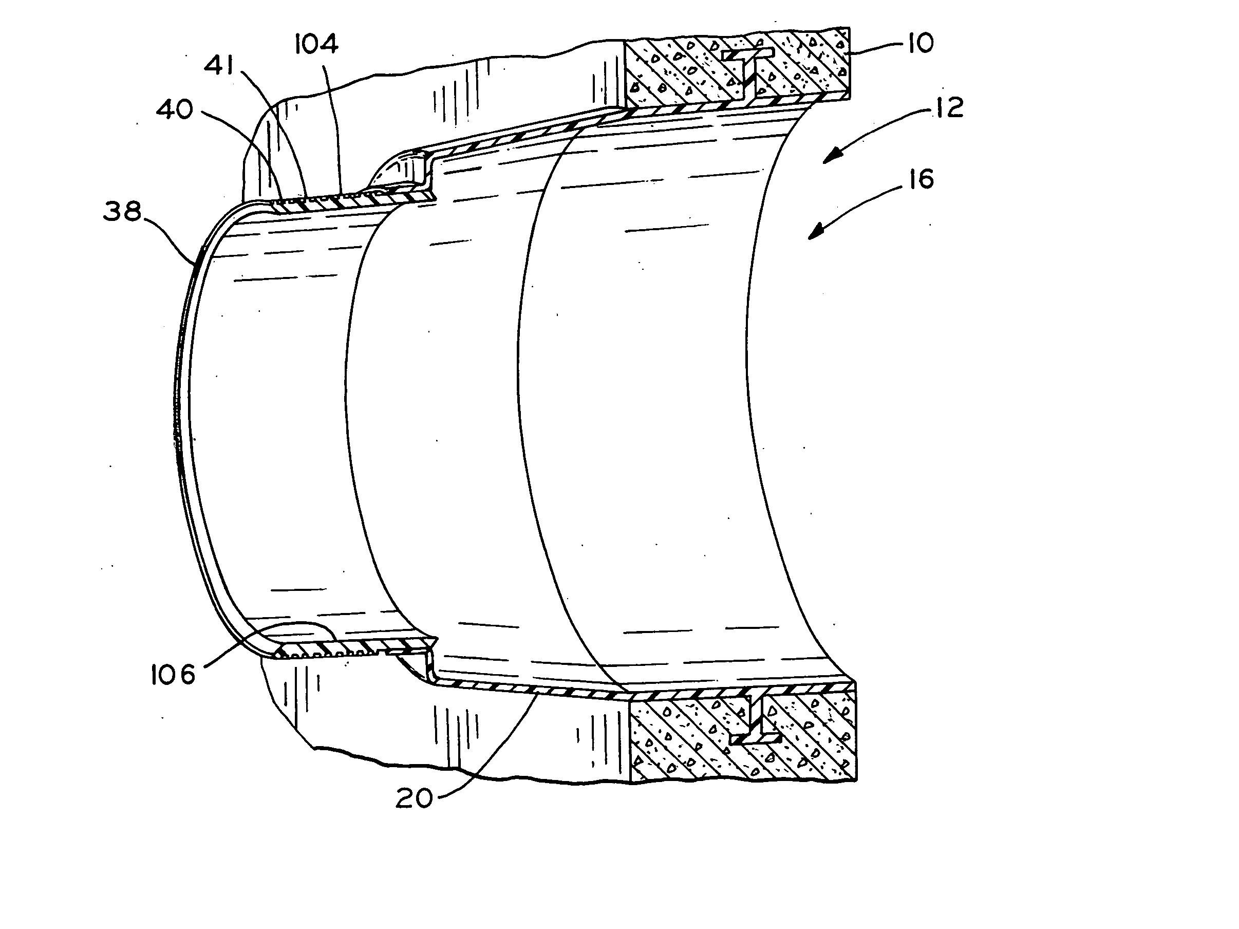
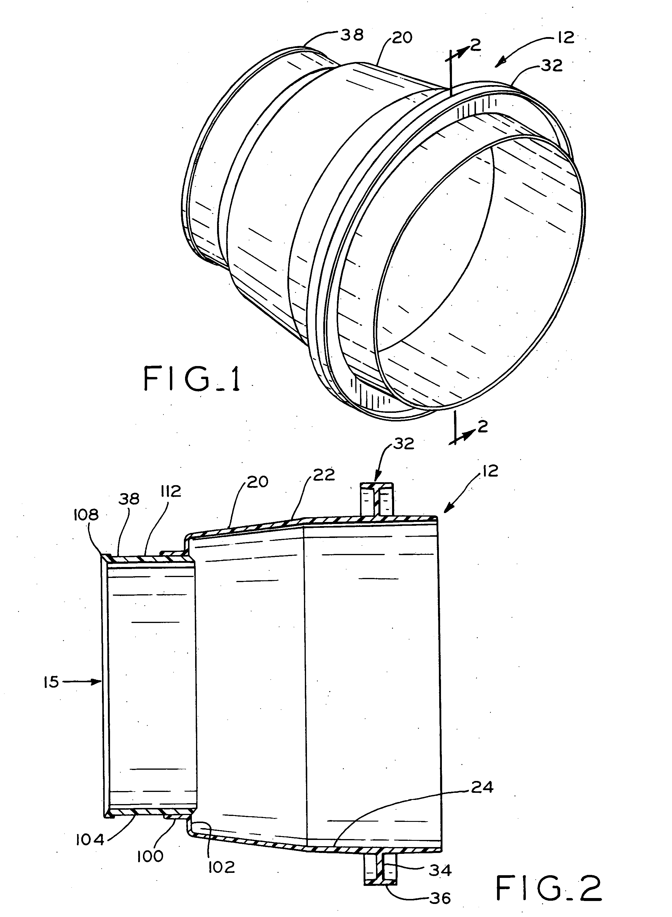
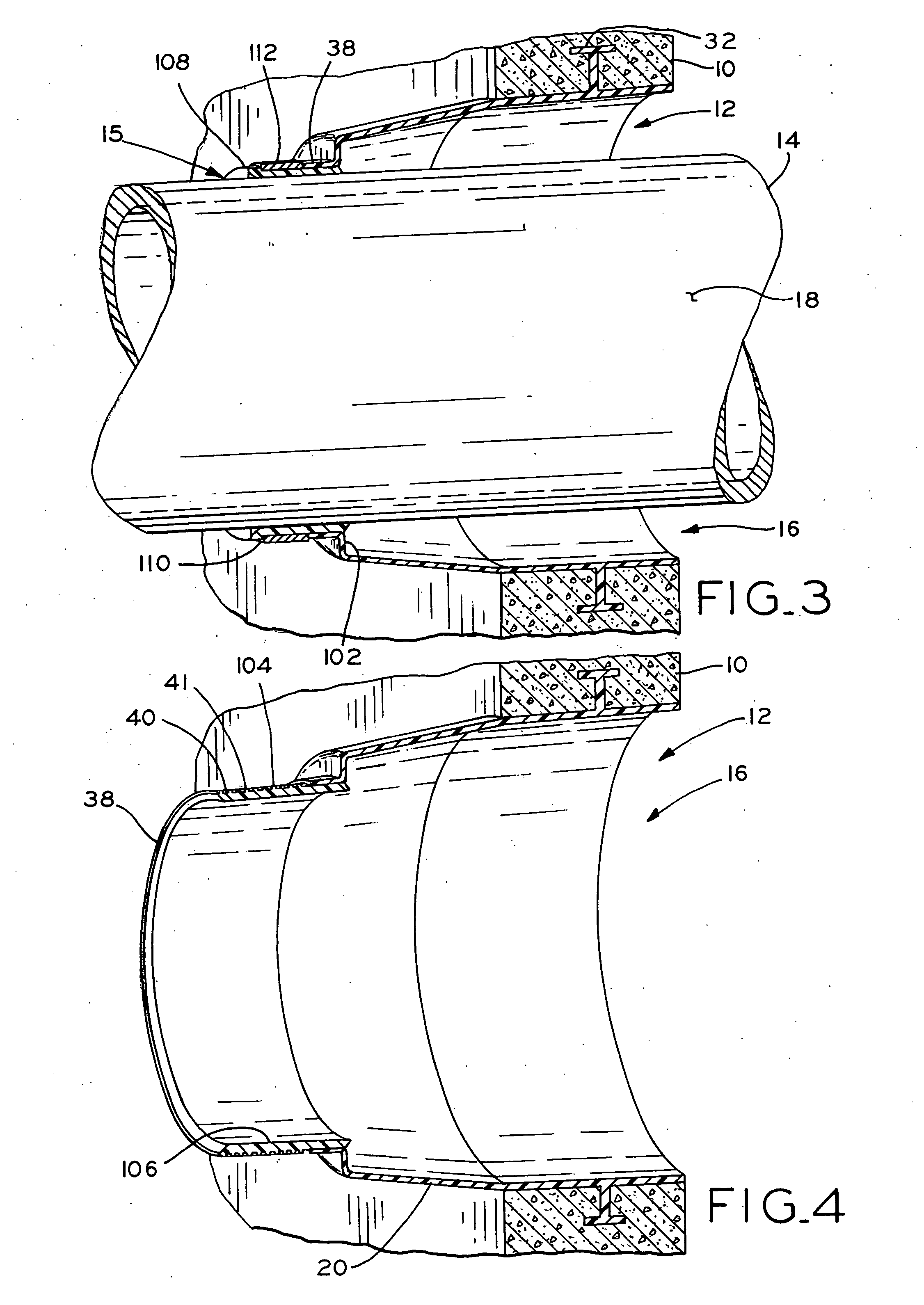
[0032] Referring first to FIG. 3, a pipe joint is shown, including a concrete structure 10 such as a manhole riser, in which at least a portion of gasket 12 is embedded. Concrete structure 10 is provided with opening 16 and gasket 12 is provided with opening 15 through which pipe 14 is received. Pipe 14 extends through gasket 12 and gasket 12 provides a fluid tight seal between concrete structure 10 and pipe 14. As described below, gasket 12 is constructed such that the fluid tight seal between structure 10 and pipe 14 is maintained even if the diameter of pipe 14 varies slightly from the diameter of opening 15 of gasket 12, or if pipe 14 is angled as it extends through opening 15. Opening 15, and thus gasket 12 and pipe 14, may have any suitable diameter, depending on the particular application.

[0033] Although the pipe joint application shown in FIG. 3 and described below is between a pipe and a concrete structure such as a manhole riser, the present gasket may generally be used i...


PUM


Abstract

A gasket which may be cast in place within a concrete structure, such as a manhole riser or septic tank, for example, to seal a connection between a pipe and the concrete structure. The gasket includes a main body portion and a sealing portion which are made from different materials. The main body portion may be made of a substantially rigid material, such as a semi-rigid plastic, for example. The sealing portion, which is united with the body portion, may be made of a substantially resilient material, such as flexible plastic or a rubber-type material, for example. In this manner, the substantially rigid portion of the gasket provides for effective anchoring in a cast wall, and the substantially resilient portion is compressible to provide a robust seal with a pipe that is inserted through the gasket.

Description

CROSS REFERENCE TO RELATED APPLICATIONS [0001] This application claims the benefit under Title 35, U.S.C. § 119(e) of U.S. Provisional Patent Application Ser. No. 60 / 607,615, entitled PIPE JOINT GASKET, filed on Sep. 7, 2004.BACKGROUND OF THE INVENTION [0002] 1. Field of the Invention [0003] The present invention relates to gaskets for use in pipe joint applications in which a gasket seals a connection between an opening in a structure and a pipe extending through the opening. [0004] 2. Description of the Related Art [0005] Pipe joint gaskets are well known in the art for sealing a pipe joint connection between a pipe and a structure to which the pipe is connected. In one particular application, a pipe joint is formed between a sewer pipe and a concrete manhole riser, for example, in which a sewer pipe is inserted through a gasket embedded within the concrete wall of the manhole riser. In other applications, pipe joints may be provided to connect pipes to septic tanks, for example, ...

Claims


Application Information

Patent Timeline
Patent Type & Authority Applications(United States)
IPC IPC(8): F16L49/00
CPCE04G15/061F16L5/02
Inventor HAPPEL, ANDREW J.
Owner PRESS SEAL GASKET
Learn More