
Liquid droplet ejection apparatus, method for manufacturing electro-optic device, electro-optic device, and electronic equipment

a technology ejection head, which is applied in the direction of typewriters, printing, instruments, etc., can solve the problems of ejection defect of functional liquid droplet ejection head, variable amount of ejected functional liquid, and long time-consuming of liquid droplet ejection apparatus known, so as to reduce the stop time of the functional liquid droplet ejection head due to the movement of the head unit, reduce the ejection defect of functional liquid drop

Inactive Publication Date: 2006-03-09
KATEEVA
View PDF5 Cites 30 Cited by
  • Summary
  • Abstract
  • Description
  • Claims
  • Application Information

AI Technical Summary

Benefits of technology

[0007] Accordingly, it is an advantage of the invention to provide a liquid droplet ejection apparatus, a method for manufacturing an electro-optic device, an electro-optic device, and an electronic equipment for reducing an ejection defect of a functional liquid droplet ejection head by reducing the stop time of the ejection of the functional liquid droplet ejection head and the tact time of the process.
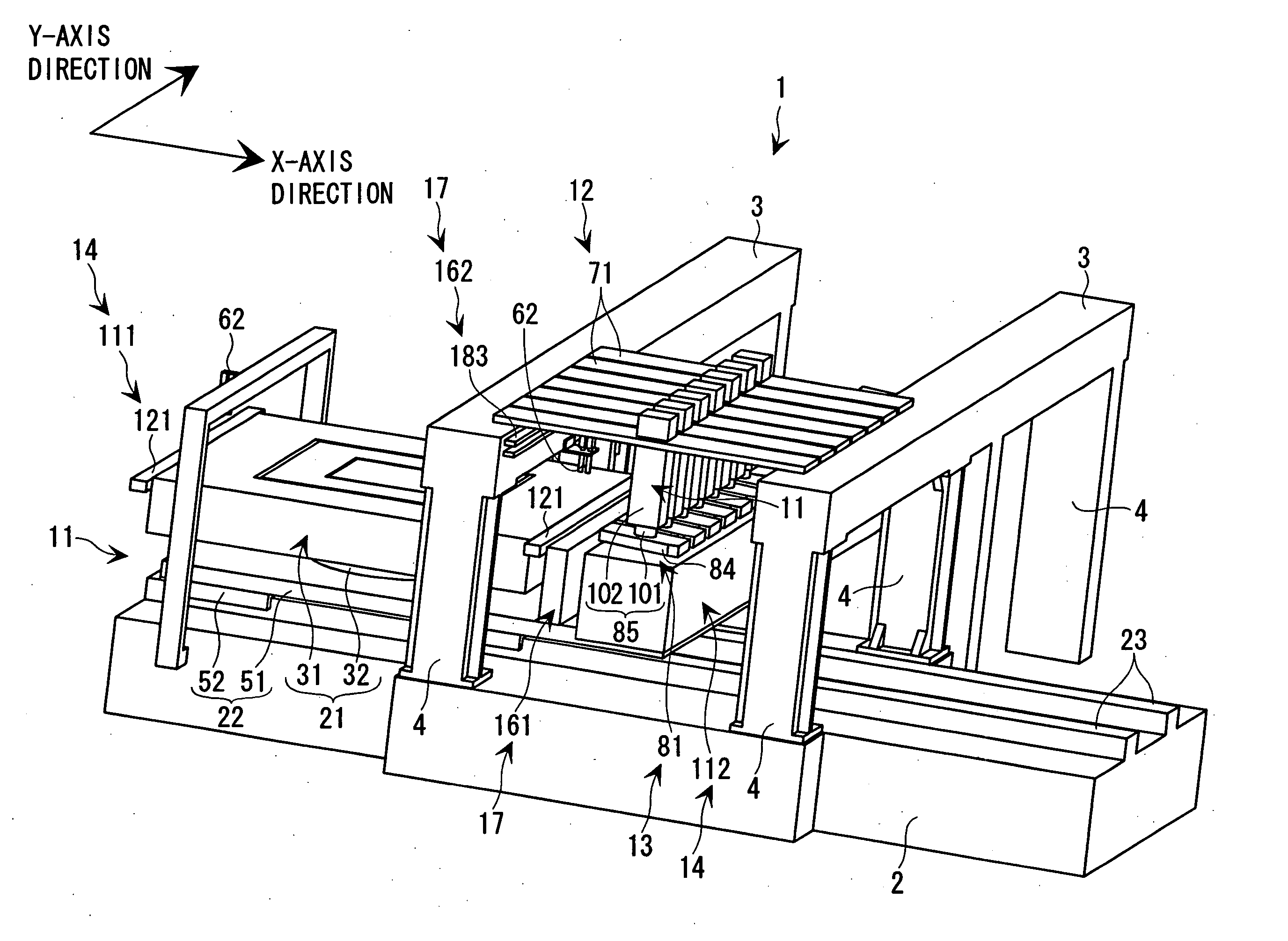
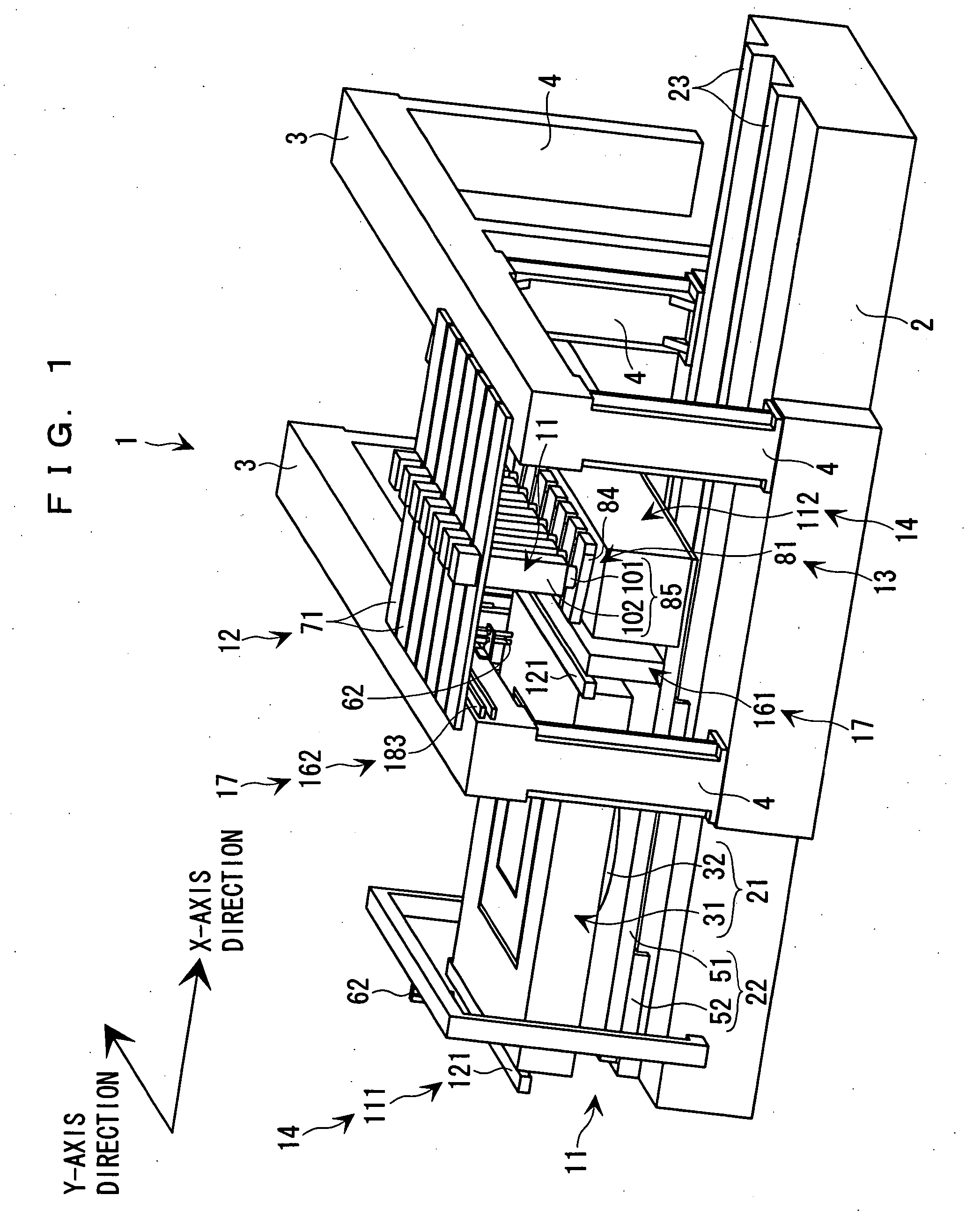
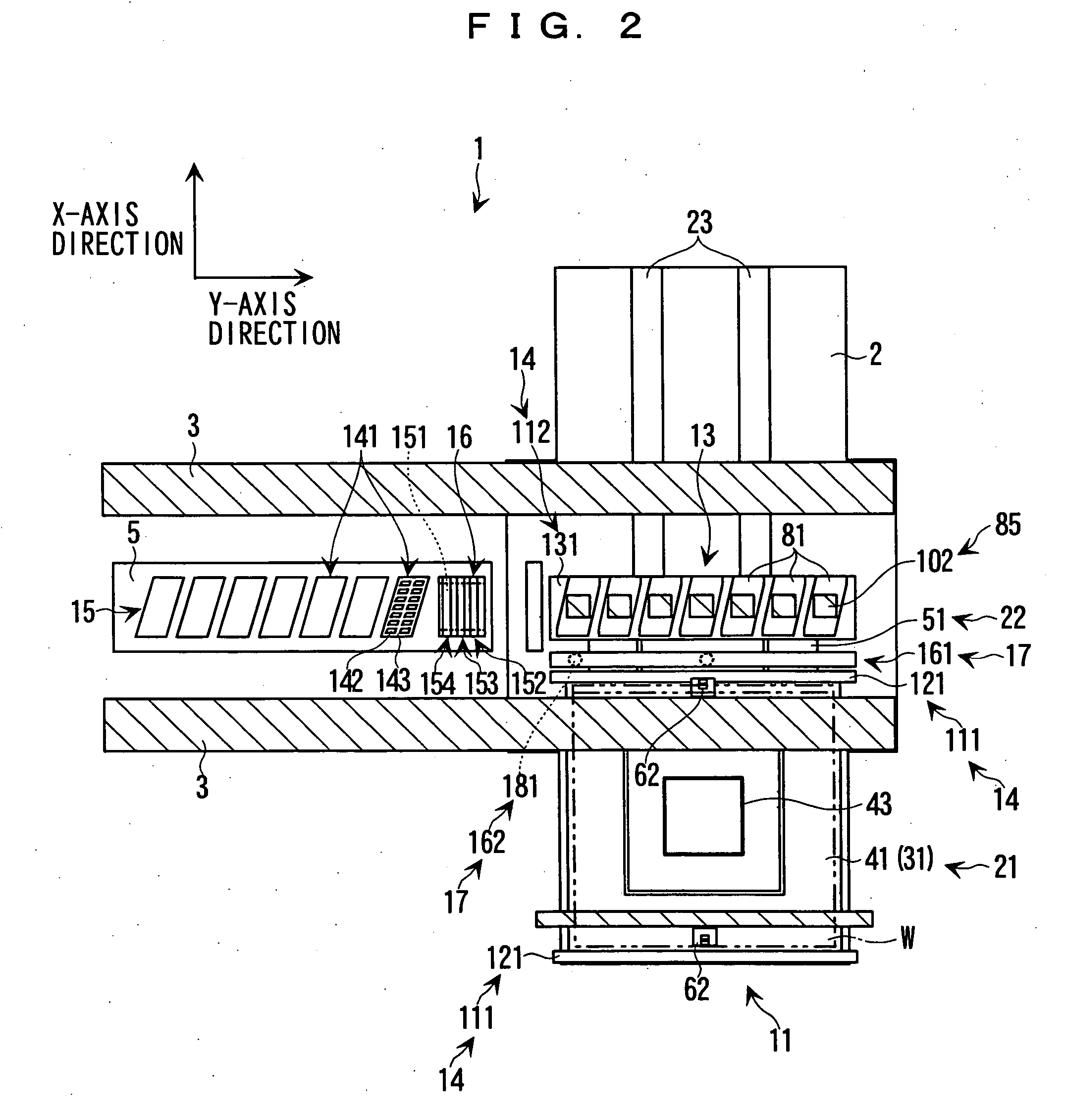
[0008] According to one aspect of the invention, there is provided a liquid droplet ejection apparatus for performing a drawing operation on a workpiece set on a set table by driving the ejection of a functional liquid droplet ejection head mounted in a head unit. The functional liquid droplet ejection head includes a plurality of ejection nozzles and the head unit is moved in a drawing area in a main scanning direction relative to the set table located in the drawing area by main scan moving means. The apparatus comprises: a periodic flushing unit disposed on a main scan moving axis offset from the drawing area towards the main scanning direction, the periodic flushing unit receiving forcible ejection from all of the ejection nozzles of the functional liquid droplet ejection head during non-drawing time; and a pre-drawing flushing unit disposed adjacent to the set table, the pre-drawing flushing unit facing the drawing area, the pre-drawing flushing unit receiving forcible ejection from all of the ejection nozzles of the functional liquid droplet ejection head, the forcible ejection being performed immediately before starting the drawing operation on the workpiece.
[0009] According to this arrangement, since the periodic flushing unit is disposed on a main scan moving axis shifted from the drawing area towards the main scanning direction, the apparatus allows the head unit to face the periodic flushing unit by using a moving axis of the head unit (i.e., the main scan moving means). Consequently, the head unit can efficiently use a relative movement of the head unit in the main scanning direction for drawing on the workpiece in order to face the periodic flushing unit, and therefore, the time required for the head unit to move between the drawing area and the periodic flushing unit can be reduced. As a result, the stop time of the functional liquid droplet ejection head due to the movement of the head unit can be reduced, thus maintaining the functional liquid droplet ejection head in good ejection conditions.
[0010] When the head unit moves from the periodic flushing unit to the drawing area, the ejection of the functional liquid droplet ejection head stops for only a short time. However, since the pre-drawing flushing unit is disposed adjacent to the set table for holding the workpiece, the forcible ejection can be performed immediately before the start of the drawing operation on the workpiece. Thus, the functional liquid droplet ejection head can be in stable ejection conditions before the drawing operation on the workpiece. As a result, the drawing operation can be precisely performed.
[0011] In this case, the main scan moving means preferably supports the set table, the periodic flushing unit, and the pre-drawing flushing unit and moves these components in the main scanning direction relative to the head unit.
[0012] According to this arrangement, by moving the set table, the periodic flushing unit, and the pre-drawing flushing unit in the main scanning direction, these components can face the head unit.

Problems solved by technology

Since the ejection nozzle of the functional liquid droplet ejection head is very small, even a short stop of an ejection mechanism may cause clogging of the ejection nozzle or may cause the variation in the amount of ejected functional liquid.
Therefore, the known liquid droplet ejection apparatus requires a long time from the completion of the drawing process to the start of the periodic flushing process and from the completion of the periodic flushing process to the start of another drawing process.
That is, since the stop time of the ejection of the functional liquid droplet ejection head increases, an ejection defect of the functional liquid droplet ejection head tends to occur.
Furthermore, the round-trip time of the head unit moving between the liquid droplet ejection area and the liquid reservoir for each drawing process increases the tact time of total processing, thus decreasing the processing efficiency.

Method used


Image

  • Liquid droplet ejection apparatus, method for manufacturing electro-optic device, electro-optic device, and electronic equipment
  • Liquid droplet ejection apparatus, method for manufacturing electro-optic device, electro-optic device, and electronic equipment
  • Liquid droplet ejection apparatus, method for manufacturing electro-optic device, electro-optic device, and electronic equipment

Examples


Embodiment Construction

[0057] A liquid droplet ejection apparatus according to the invention is described below with reference to the accompanying drawings. The liquid droplet ejection apparatus is used in a manufacturing line of a flat display. By adopting the liquid droplet ejection method using a functional liquid droplet ejection head, the liquid droplet ejection apparatus is used to manufacture a color filter of a liquid crystal display device for three colors, namely, red (R), green (G), and blue (B), or light emitting elements functioning as pixels of an organic electroluminescent (EL) display on a workpiece (substrate).

[0058] As shown in FIGS. 1 through 3, a liquid droplet ejection apparatus 1 is installed on an X-axis support base 2 (stone bed). The liquid droplet ejection apparatus 1 includes an X-axis table 11 (main scan moving means) which extends in the X-axis direction (main scanning direction) and which moves a workpiece W in the X-axis direction; a Y-axis table 12 (sub scan moving means) ...


PUM


Abstract

A liquid droplet ejection apparatus performs a drawing operation on a workpiece set on a set table by driving the ejection of a functional liquid droplet ejection head in a head unit while moving the head unit in a main scanning direction relative to the set table facing a drawing area by an X-axis table. The liquid droplet ejection apparatus includes a periodic flushing unit which is disposed on a main scan moving axis at a position offset from the drawing area towards the main scanning direction and which receives forcible ejection from the functional liquid droplet ejection head during non-drawing time and a pre-drawing flushing unit which is disposed adjacent to the set table and faces the drawing area and which receives forcible ejection from the functional liquid droplet ejection head performed immediately before starting the drawing operation.

Description

BACKGROUND OF THE INVENTION [0001] 1. Field of the Invention [0002] The present invention relates to a liquid droplet ejection apparatus that ejects functional liquid from a functional liquid droplet ejection head onto a workpiece while moving a head unit including the functional liquid droplet ejection head relative to the workpiece, a method for manufacturing an electro-optic device, an electro-optic apparatus, and an electronic equipment. [0003] 2. Description of the Related Art [0004] There is known a liquid droplet ejection apparatus which is used to manufacture a variety of products (e.g., a color filter of a liquid crystal display device) by a liquid droplet ejection method using a functional liquid droplet ejection head. The liquid droplet ejection apparatus includes an X-axis direction moving mechanism which moves a substrate transport table (set table), on which a substrate (workpiece) is set, in the X-axis direction and an Y-axis direction moving mechanism which moves a h...

Claims


Application Information

Patent Timeline
IPC IPC(8): B41J23/00
CPCB41J3/28H01L51/0005B41J3/407H10K71/135G02F1/1335
Inventor KOJIMA, KENJI
Owner KATEEVA
Learn More