Luminous device and optical fixing device

a technology of luminous devices and fixing devices, applied in the field of luminous devices and optical fixing devices, can solve the problems of low printing quality and achieve the effect of reducing the number of lines

Inactive Publication Date: 2006-03-09
FUJIFILM HLDG CORP
View PDF2 Cites 25 Cited by
  • Summary
  • Abstract
  • Description
  • Claims
  • Application Information

AI Technical Summary

Benefits of technology

[0017] By making the number “q” of light emitting elements of each block equal to the line number “m”, the degree of distribution of the light emitting elements in the main scan direction is raised within the same block. So the illuminance unevenness between the blocks becomes inconspicuous. By setting q>m, the line number “m” may be reduced, which contributes to making the luminous device smaller.

Problems solved by technology

This will cause density unevenness, and thus lower the quality of printed images.

Method used


Image

  • Luminous device and optical fixing device
  • Luminous device and optical fixing device
  • Luminous device and optical fixing device

Examples


Embodiment Construction

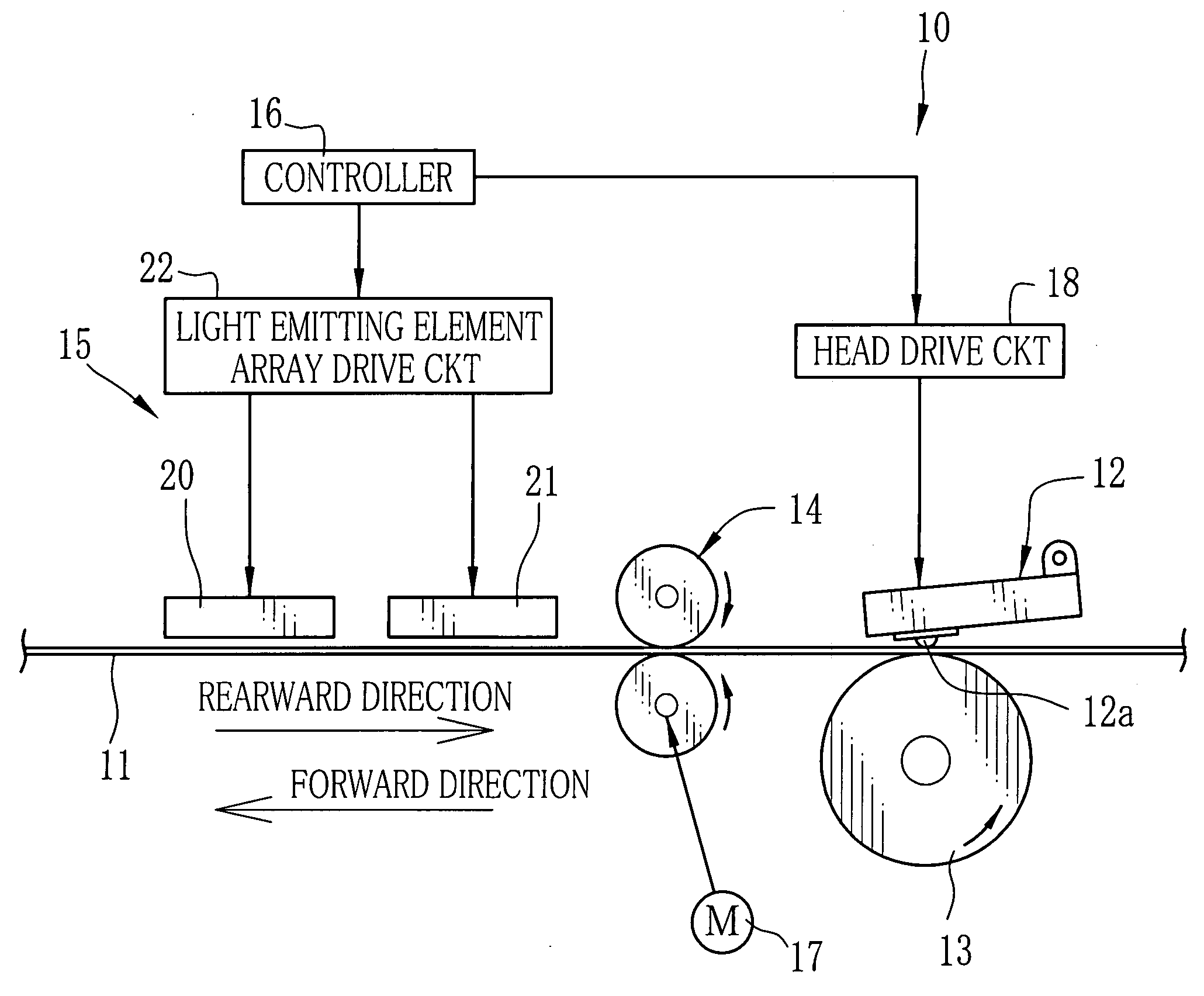
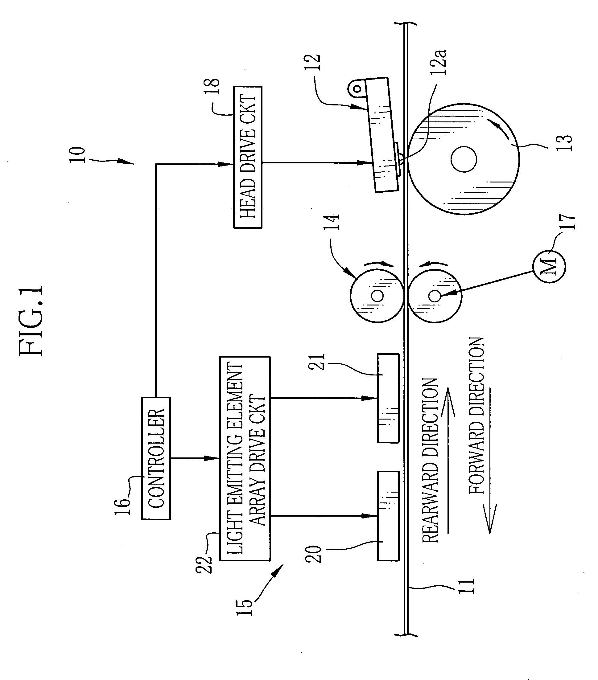
[0041] A direct heat sensitive type color thermal printer 10 carries out thermal recording and optical fixing to print a full-color image on heat sensitive color recording paper 11, hereinafter called simply the recording paper, while conveying the recording paper 11 forward and rearward. The thermal printer 10 is constituted of a thermal head 12 for heating the recording paper 11 to let its heat sensitive coloring layers develop respective colors sequentially from the obverse, a platen roller 13 placed in opposition to the thermal head 12 to support the recording paper 11, a pair of conveyer rollers 14 for conveying the recording paper 11, an optical fixing device 15 and a controller 16 for controlling the respective components of the color thermal printer 10.

[0042] The recording paper 11 has heat sensitive coloring layers for cyan, magenta and yellow, which are formed atop another on a base material in this order from the bottom. Among these heat sensitive coloring layers, the to...


PUM


Abstract

A luminous device comprises an array of LEDs aligned in a plural number “m” of lines which extend in a main scan direction, and are apposed in a sub scan direction orthogonal to the main scan direction. The array is grouped into a number of blocks to be driven block by block, each block consisting of a number “q” of LEDs connected in serial to one another, wherein q=m. Where the numbers “q” and “m” are five and two respectively, two or three of the five LEDs of the same block are located in one of the two lines (L1), whereas other LEDs of that block are located in the other line (L2), such that the LEDs of the different blocks are located substantially in the same column in the sub scan direction, to distribute the LEDs of the same block in the main scan direction. Thereby, unevenness in integral illuminance in the sub scan direction is reduced even if there are illuminance variations between the blocks.

Description

FIELD OF THE INVENTION [0001] The present invention relates to a luminous device that has a plural blocks of light emitting elements which are connected in serial to each other in each block, so as to activate the light emitting elements block by block. The present invention also relates to an optical fixing device for a direct color thermal printer, using the luminous device. BACKGROUND ARTS [0002] The direct color thermal printer uses heat sensitive color recording paper that has at least three heat sensitive coloring layers that develop different colors and are formed atop another. The coloring layers have the lower heat sensitivity as they are formed in the lower position from an obverse surface. The first and second coloring layers from the obverse surface are designed to be fixed by ultraviolet rays of respective specific wavelength ranges. While the heat sensitive color recording paper is being conveyed back and forth, a thermal head is pressed on the recording paper to heat ...

Claims


Application Information

Patent Timeline
Patent Type & Authority Applications(United States)
IPC IPC(8): B41J2/385G03G13/04
CPCB41J2/4753B41J2/45
Inventor KOKUBO, HIDEYUKI
Owner FUJIFILM HLDG CORP
Why Eureka
Try Eureka