Image capture device and image data correction process of image capture device

a technology of image data and image capture device, which is applied in the field of image capture device and image data correction process at the image capture device, can solve the problems inability to accurately output signals, and inability to guarantee the memory capacity of the second memory unit, etc., to achieve high image quality, reduce the effect of deterioration of image quality and reducing the number of deterioration of pixels

Active Publication Date: 2006-03-09
FUJIFILM CORP +1
View PDF8 Cites 60 Cited by
  • Summary
  • Abstract
  • Description
  • Claims
  • Application Information

AI Technical Summary

Benefits of technology

[0023] The first memory unit can compress and memorize position information of defective pixels at the solid-state image capture unit. When the exposure duration information that the duration information provision unit provides is exposure information representing an exposure duration of equal to or greater than less than the pre-specified duration, the correction unit corrects, of the image data obtained by the image capture unit, image data that corresponds to defective pixels according to both the position information which is decompressed from the compressed position information memorized at the first memory unit and the non-compressed position information which is memorized at the second memory unit. Accordingly, because the position information of defective pixels of the solid-state image capture component that is stored at the second memory unit is compressed and memorized, memory capacity of the second memory unit can be assured. Further, the decompression of compressed position information is carried out only for correction processing of defective pixels at a time of acquisition with an exposure duration longer than the predetermined duration. Thus, it ...

Problems solved by technology

Among such photoelectric conversion elements, there may be defects (defective pixels) due to adhesion of dust, damage and the like, and due to crystal defects and the like.
Hence, it may not be possible to output signals which accurately correspond to light amounts of incident light with these defective pixels.
On the other hand, a defective pixel which arises due to a crystal defect...

Method used


Image

  • Image capture device and image data correction process of image capture device
  • Image capture device and image data correction process of image capture device
  • Image capture device and image data correction process of image capture device

Examples


first embodiment

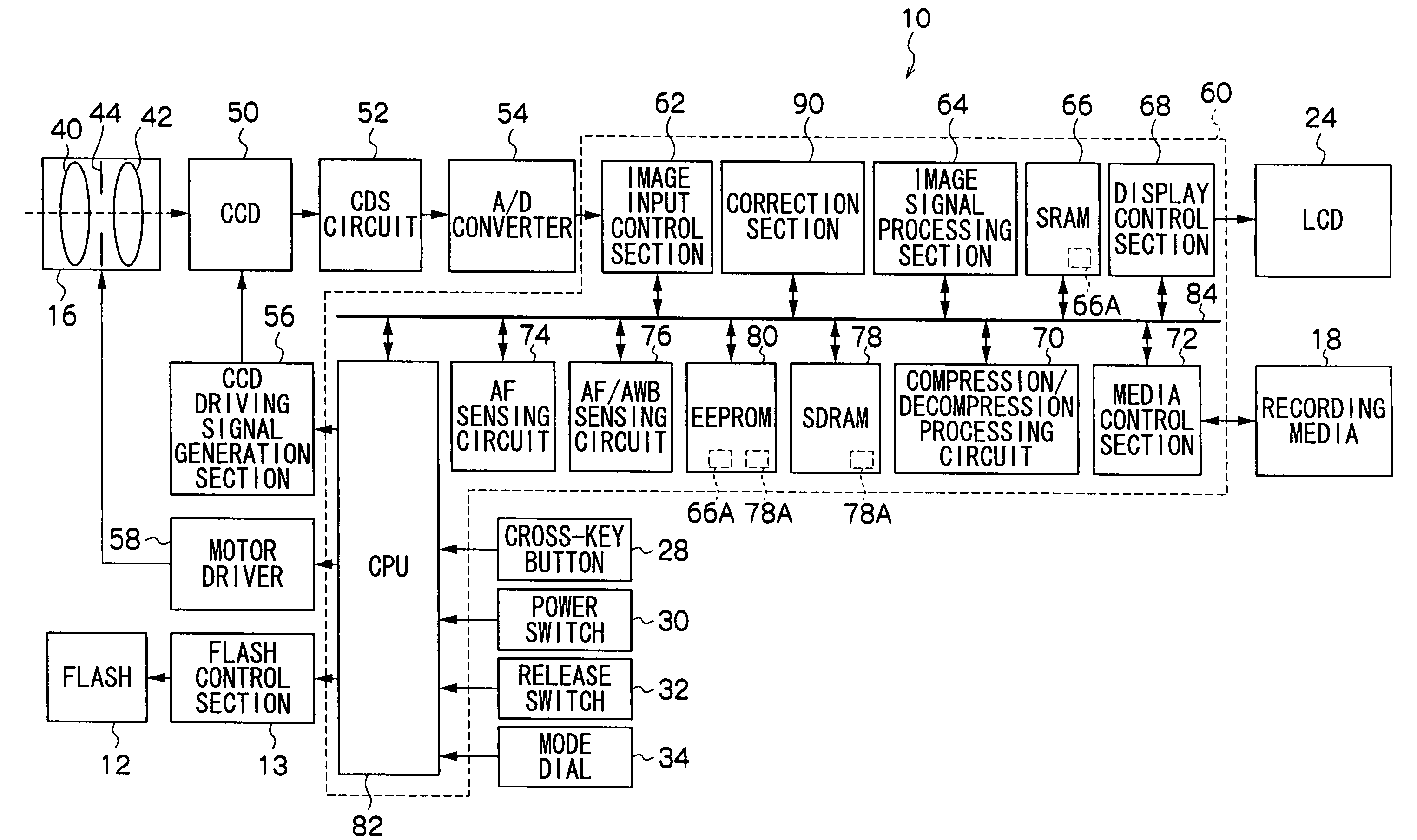
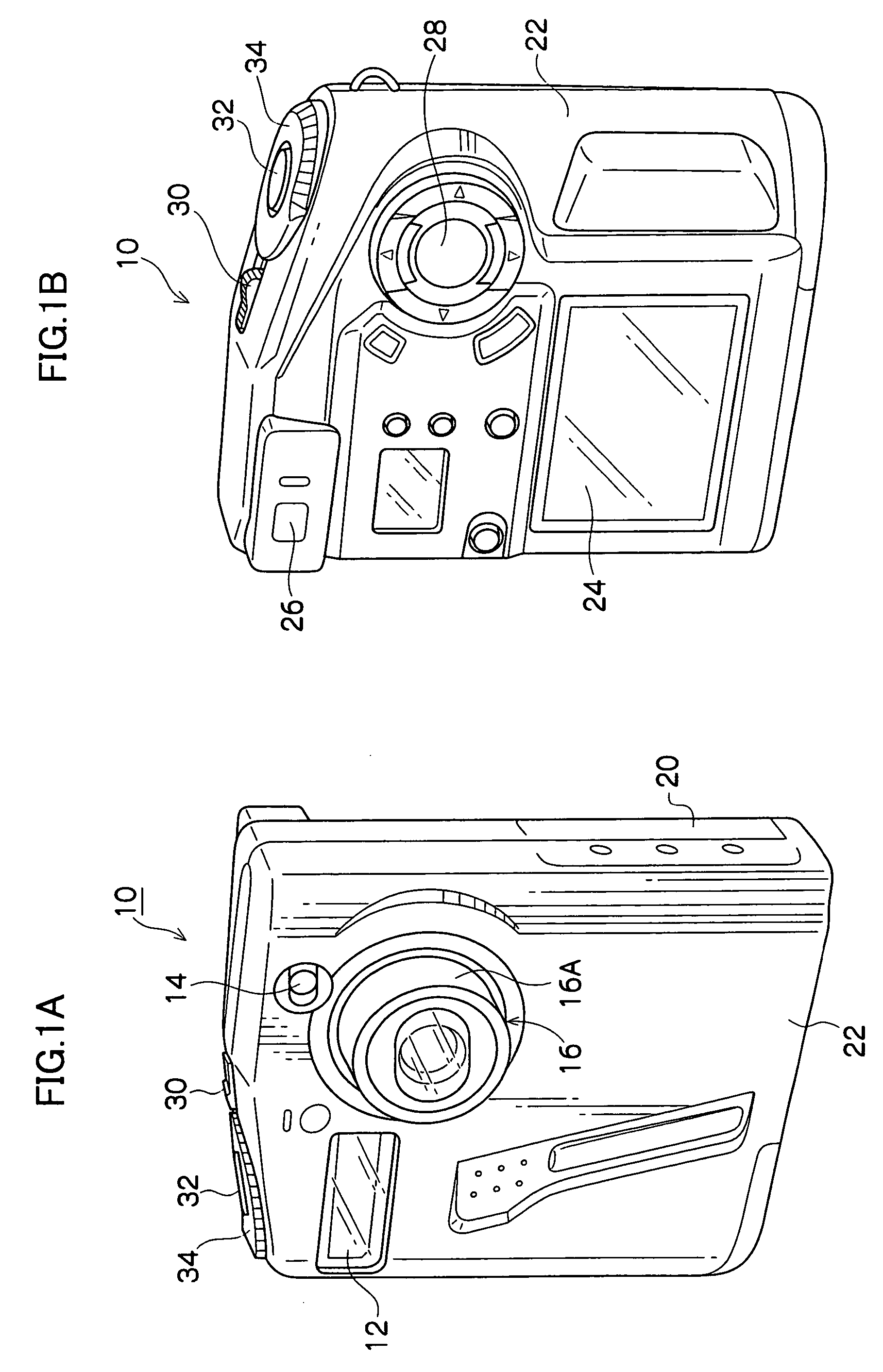
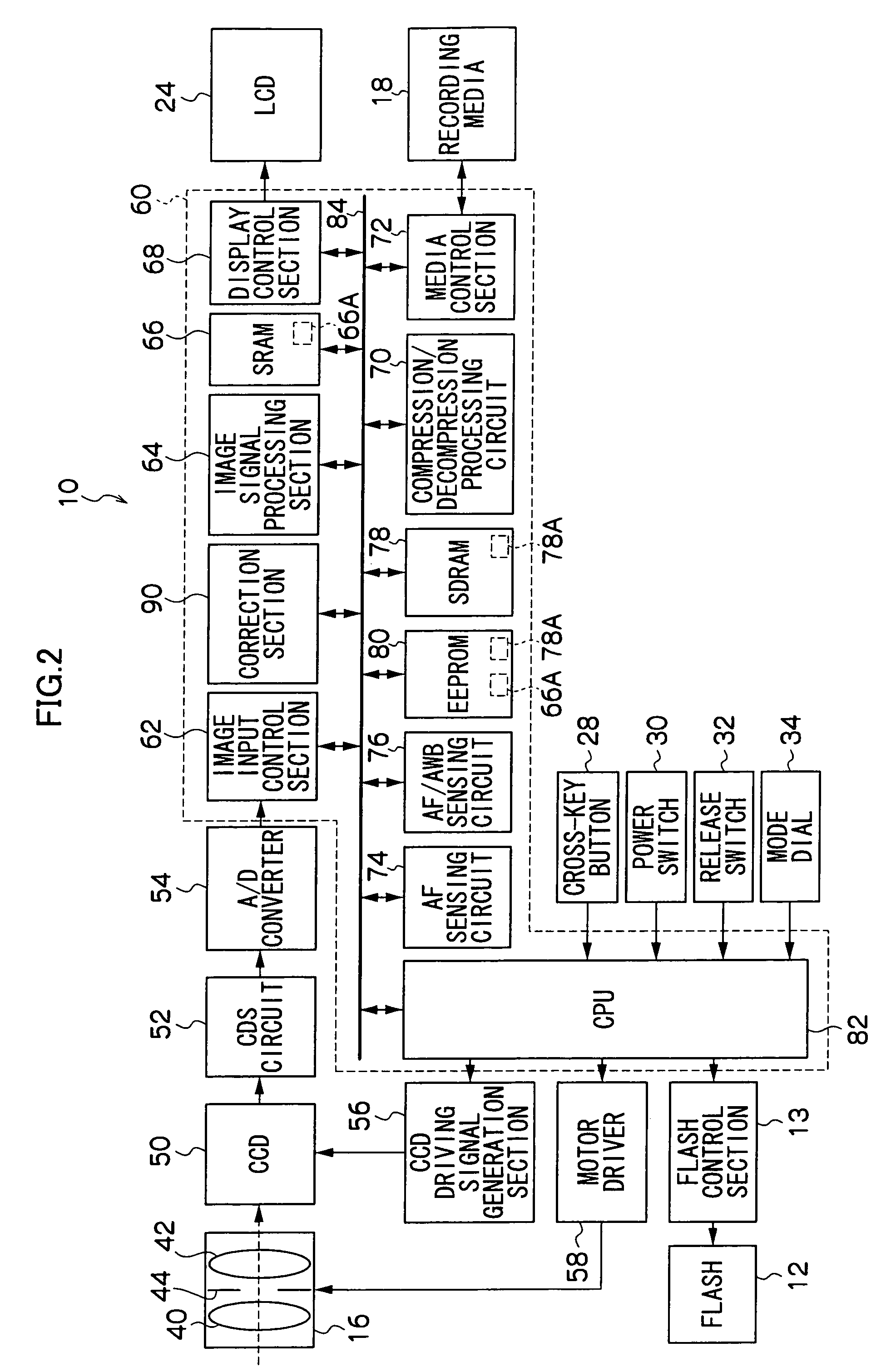
[0032] As shown in FIG. 1A, a flash 12, a viewfinder window 14 and an optical unit 16 are provided at a front face of a digital camera 10 which serves as an image capture device of the present invention. The flash 12 emits light when illumination is poor. Light from a subject to be photographed is incident at the viewfinder window 14. The optical unit 16 is for focusing a subject image. A slot 20 is provided at a side face of the digital camera 10. A portable recording media 18 (see FIG. 2), which records images obtained by photography as digital data, can be mounted at the slot 20.

[0033] The optical unit 16 is a retracting-type optical lens, which is retracted inside a casing 22 of a main body of the digital camera 10 except at times of photography. At times of photography, an extendable barrel 16A is extended along an optical axis and, as shown in FIG. 1A, the barrel 16A is exposed outside the casing 22. The optical unit 16 includes, inside the barrel 16A, an imaging lens 40, a f...

second embodiment

[0068] For the first embodiment described above, a case has been described of performing pixel correction of defective pixels which have static characteristics, at which generated noise components are substantially constant irrespective of the length of a duration of exposure. For the present embodiment however, a case will be described of performing correction on both defective pixels which have dynamic characteristics, such as thermal white flaws and the like at which the amount of a noise component which is generated by a defective pixel increases as an exposure duration becomes longer, and defective pixels having static characteristics, as have been discussed for the above-described first embodiment.

[0069] Furthermore, for the first embodiment described above, respective memorization of the continuous defect correction LUT 66A and the isolated defect correction LUT 78A as a plurality of LUTs at the EEPROM 80 has been described. For the present embodiment however, prior memoriza...


PUM


Abstract

An image capture device provided with a first memory unit, which memorizes position information of non-continuous defective pixels of a solid-state image capture component, and a second memory unit with a higher access rate than the first memory unit, which memorizes position information of continuous defective pixels. When a continuous photography mode or a video photography mode is set, defective pixel correction processing is carried out on image data corresponding to each of defective pixels according to the defective pixel position information stored at the second memory unit. Alternatively, when a still photography mode is set, image data corresponding to all defective pixels is corrected, based on both the defective pixel position information stored at the first memory unit and the defective pixel position information stored at the second memory unit. As a result, it is possible to correct defective pixels with high efficiency in accordance with conditions of photography.

Description

CROSS-REFERENCE TO RELATED APPLICATION [0001] This application claims priority under 35 USC 119 from Japanese Patent Application No. 2004-242288, the disclosure of which is incorporated by reference herein. BACKGROUND OF THE INVENTION [0002] 1. Field of the Invention [0003] The present invention relates to an image capture device and an image data correction process at the image capture device, and more particularly to an image capture device such as a digital camera or the like. [0004] 2. Description of the Related Art [0005] Conventionally, solid-state image capture components of digital cameras, which serve as image capture devices, convert light corresponding to subjects to electronic signals by photoelectric conversion with pluralities of photoelectric conversion elements, and output the electronic signals. Among such photoelectric conversion elements, there may be defects (defective pixels) due to adhesion of dust, damage and the like, and due to crystal defects and the like. ...

Claims


Application Information

Patent Timeline
IPC IPC(8): H04N9/64H04N5/232H04N5/335H04N5/367H04N101/00
CPCH04N5/2252H04N9/646H04N5/367H04N23/51H04N25/68
Inventor IRIE, KOUSUKE
Owner FUJIFILM CORP
Why Eureka
Try Eureka