Metallized film capacitor

a technology of metal film capacitors and capacitors, which is applied in the direction of capacitors, fixed capacitor details, electrical equipment, etc., can solve the problems of increasing the temperature of the capacitor and lowering the self-maintenance function instead, so as to reduce the heat generated, and reduce the effect of heat generated

Active Publication Date: 2006-03-09
PANASONIC CORP
View PDF5 Cites 29 Cited by
  • Summary
  • Abstract
  • Description
  • Claims
  • Application Information

AI Technical Summary

Benefits of technology

[0014] This structure allows a current running through a first deposited electrode to decrease as it approaches to the insulation margin, so that the current running through the fuse can be reduced, thereby decreasing the heat generated. Further, the other side of the insulation margin has a second deposited electrode of which electrode is divided and has fuse, so that even if a short occurs at any place of effective electrodes, the fuse is blown-out and then isolated from the electric circuit, i.e., a self-maintaining function is obtainable.
[0015] In the case of dividing lattice-like effective electrodes of the deposited electrode approaching to the insulation margin, the heat generated can be more substantially reduced comparing with the prior art which divides a deposited electrode in a lattice form uniformly.
[0016] In the case of dividing the deposited electrode having the heavy-edge structure and approaching to the insulating margin, the heat generated can be also substantially reduced.

Problems solved by technology

However, although the conventional metallized-film capacitor discussed above achieves a self-maintaining function using a fuse function, the fuse generates heat because of a current running during the operation, so that a temperature of the capacitor increases.
This is a crucial problem.
A wider width of the fuse or parallel arrangement of the fuses will reduce the heat; however, those measures lower the self-maintaining function instead.
When this capacitor is used in an automobile among others, this problem becomes crucial because the environmental temperature is basically high.

Method used


Image

  • Metallized film capacitor
  • Metallized film capacitor
  • Metallized film capacitor

Examples


exemplary embodiment 1

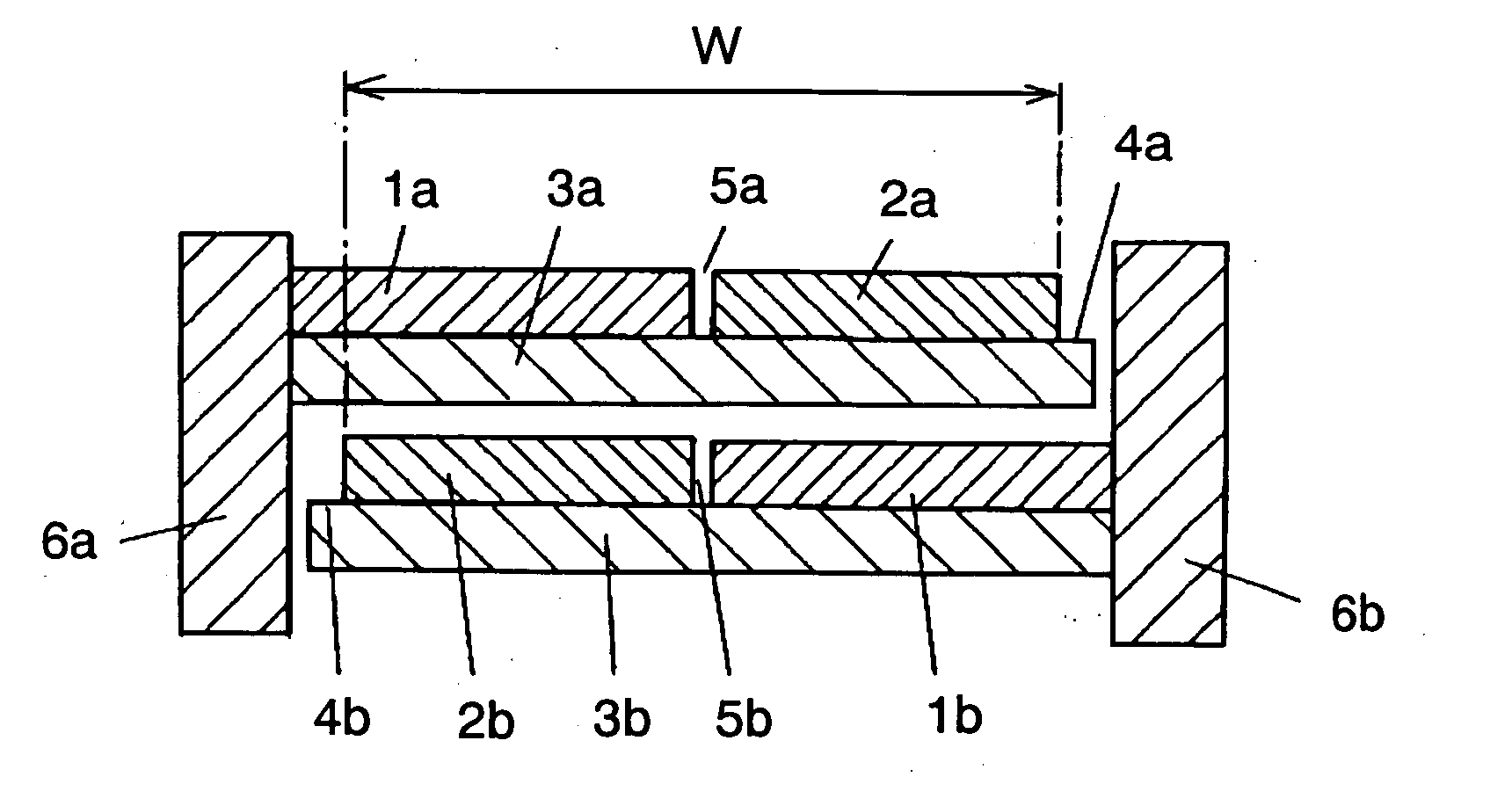
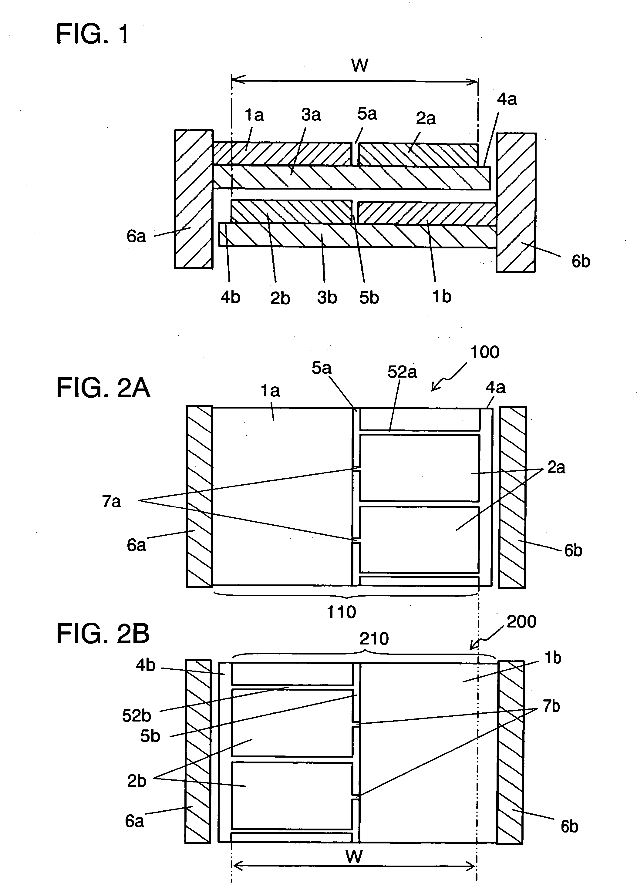
[0042]FIG. 1, FIGS. 2A and 2B show first metallized-film 100 and second metallized-film 200, which are elements of a winding-type metallized-film capacitor. Those films include a pair of deposited electrodes 110 and 210 formed by depositing aluminum in a pattern on respective one face of dielectric films 3a and 3b, and insulation margin 4a, 4b occupying respective one edge of dielectric films 3a, 3b. Electrodes are led out from the pair of deposited electrodes 110 and 210 through metallized contacts 6a, 6b disposed respectively on either one of the end-faces.

[0043] Deposited electrodes 110, 210 have non-deposited slits 5a, 5b respectively at approx. center of the width (W) of an effective electrode forming a capacitance. Slits 5a, 5b do not have deposited electrodes and are formed by transferring patterned oil onto the dielectric film before the deposition. As FIGS. 2A, 2B show, deposited electrodes 110, 210 include plural divisional electrodes 2a, 2b between insulation margins 4a,...

exemplary embodiment 2

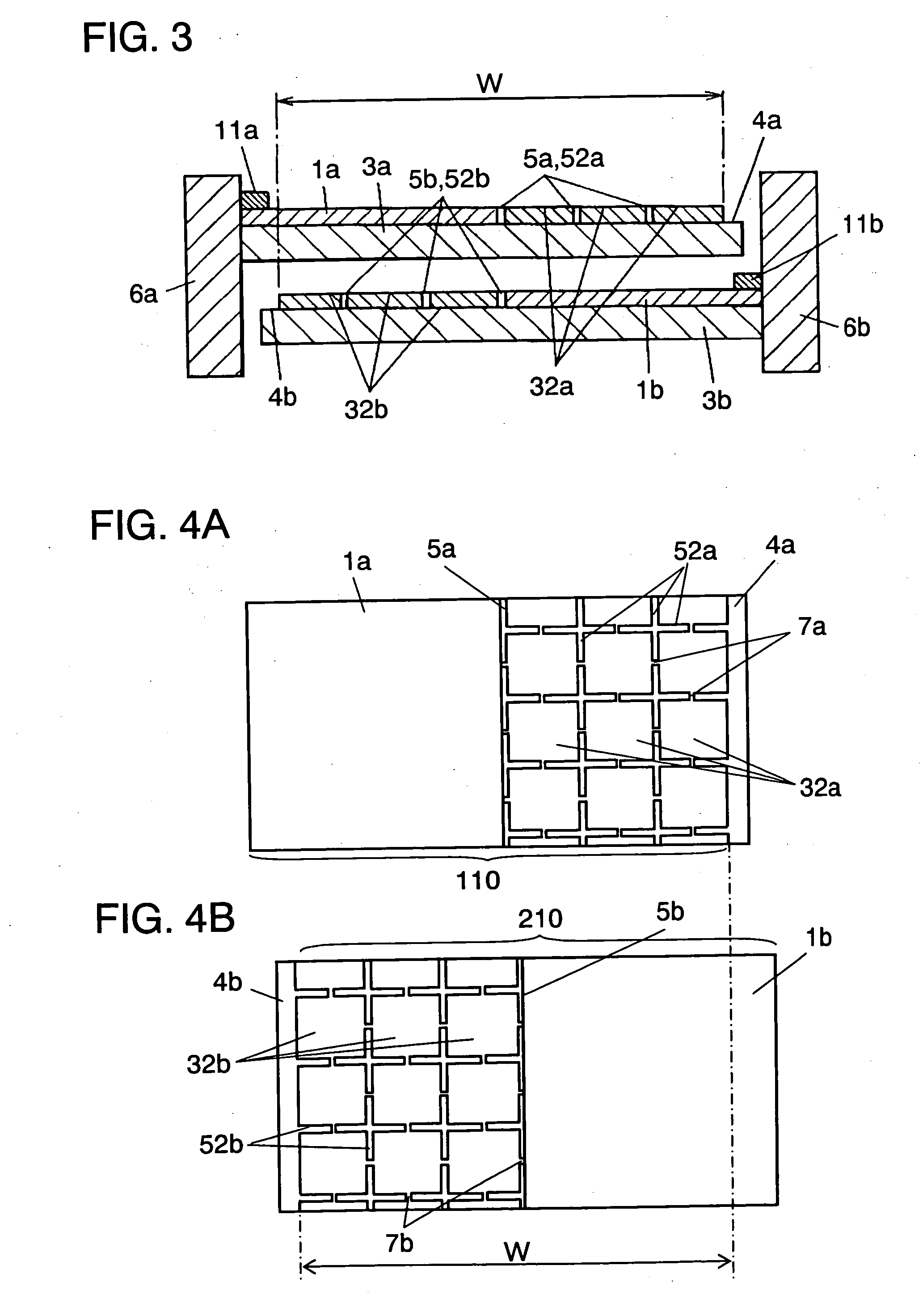
[0045] The second embodiment differs from the first one in having lattice-like divisional deposited electrodes at the respective places between the approx. center of the width of effective electrode and the insulation margin. Similar elements to those in the first embodiment have the same reference marks, and only the different points between the second embodiment and the first one are demonstrated hereinafter.

[0046] As shown in FIG. 3, FIGS. 4A and 4B, deposited electrodes 110, 210 of the metallized-film capacitor in accordance with the second embodiment include slits 5a, 5b at approx. center of the width (W) of respective effective electrodes which form the capacitance. Electrodes 110, 210 also include slits 52a and 52b, having no deposited electrodes, at the places between the center and insulation margins 4a and 4b. Plural lattice-like divisional electrodes 32a, 32b are divided by slits 52a, 52b, and coupled in parallel respectively to each other by fuses 7a, 7b. On the other h...

exemplary embodiment 3

[0048] The third embodiment differs from the first one in preparing a pair of deposited electrodes on both faces of a first dielectric film and no metal deposited at all on a second dielectric film. Similar elements to those in the first embodiment have the same reference marks, and only the different points between the third embodiment and the first one are demonstrated hereinafter.

[0049] As shown in FIG. 5, FIGS. 6A and 6B, a metallized-film capacitor in accordance with the third embodiment includes dielectric film 53a having deposited electrodes 110, 210 formed on its both the faces, and dielectric film 53b having no deposition. Both of films 53a and 53b overlap each other, and electrodes 110, 210 are coupled respectively to metallized contacts 6a, 6b formed respectively on either one of the end faces. Electrodes 110, 210 include slits 5a, 5b at approx. center of the width (W) of the effective electrodes which form the respective capacitance, and are divided by slits 52a, 52b ha...


PUM


Abstract

A metallized-film capacitor includes a slit (5a) at approx. center of the width (W) of an effective electrode which actually forms a capacitance of a pair of deposited electrodes (110, 210). Divisional electrodes (2a, 2b) exist at a place between the center and insulation margins (4a, 4b), and the electrodes (2a, 2b) are coupled in parallel to each other by fuses (7a, 7b) disposed away from metallized contacts (6a, 6b). Such a structure as placing fuses (7a, 7b) away from the contacts (6a, 6b) allows reducing a current supplied from the contacts (6a, 6b) and running through fuses (7a, 7b), thereby lowering heat generated from fuses (7a, 7b). As a result, a temperature rise in the metallized-film capacitor can be suppressed.

Description

TECHNICAL FIELD [0001] The present invention relates to metallized-film capacitors to be used in electronic devices, electric devices, industrial devices and automobiles. BACKGROUND ART [0002] There are generally two major products in metallized-film capacitors; the one uses metallic foil as its electrodes, and the other one uses metal deposited on dielectric film as its electrodes. The metallized-film capacitor using deposited metal as the electrodes (hereinafter referred to as a deposited electrode), in particular, can be downsized because of its smaller electrodes than those of the other one, i.e. the capacitor using metallic foil as electrodes, and is more reliable with respect to dielectric breakdown because of its self-healing performance proper to the deposited electrode, so that it has been widely used. Meanwhile, the self-healing performance can recover the function of a capacitor when a short occurs at a defective insulation, because an energy produced at the short vaporiz...

Claims


Application Information

Patent Timeline
Patent Type & Authority Applications(United States)
IPC IPC(8): H01G4/005H01G4/18H01G2/16H01G4/228H01G4/252
CPCH01G2/16H01G4/012H01G4/145H01G4/252H01G4/228
Inventor SHIOTA, KOHEISAITO, TOSHIHARUTAKEOKA, HIROKI
Owner PANASONIC CORP
Why Eureka
Try Eureka