Queuing system

a technology of queueing and queueing, applied in the field of queueing system, can solve the problems of adversely affecting the timely delivery and quality of new switches, and achieve the effects of increasing the amount of memory within the integrated circuit, less cost, and increasing the speed of the memory

Inactive Publication Date: 2006-03-09
CALLAHAN CELLULAR L L C
View PDF26 Cites 10 Cited by
  • Summary
  • Abstract
  • Description
  • Claims
  • Application Information

AI Technical Summary

Benefits of technology

[0027] The problems with the prior art have been overcome with this invention, which provides an improved architecture for switches. The current trends in semiconductor design suggest that increasing the amount of memory within an integrated circuit is less costly than increasing the speed of that memory. It is also well known that complex, high speed logic can present difficulties in terms of design and testing, which can adversely affect the timely delivery and quality of new switches. The present invention utilizes an increased amount of memory, operating at speeds lower than are required by Input Queued switches, and a simple scheduling algorithm. The architecture of the present invention divides the input ports into groups, where each input port group has an associated set of memory elements. Incoming packets are routed to the appropriate element in the set of memory elements. The number of groups and the number of ports that are included in each group can be varied, allowing the architecture to be modified based on the system architecture, the semiconductor technology, and other design considerations.

Problems solved by technology

It is also well known that complex, high speed logic can present difficulties in terms of design and testing, which can adversely affect the timely delivery and quality of new switches.

Method used


Image

  • Queuing system
  • Queuing system
  • Queuing system

Examples


Embodiment Construction

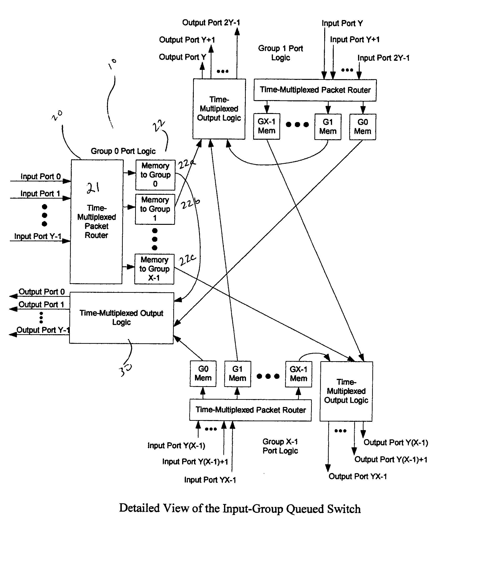
[0035] Switches are used to logically connect a set of input ports to a set of output ports. Most typically, the number of input ports is identical to the number of output ports, although this is not a requirement. FIG. 6 shows the topology of a switch in accordance with the present invention. In this figure, the number of input ports and the number of output ports are identical, and are both represented by the expression:

[0036] X multiplied by Y, where the terms X and Y will be described in more detail below.

[0037] Referring again to FIG. 6, the port logic for group 0 is generally shown at 10. Group 0 is a subset of the total number of ports contained in the device. In this embodiment, there are a number of groups, where each group represents a subset of the total number of ports. These subsets are non-overlapping, such that the each port is contained in only one group. The port logic 10 comprises logic associated with the input ports 20 and logic associated with the output ports...


PUM


Abstract

An improved architecture for switches and a method for transmitting data with the switching are disclosed. An increased amount of memory is utilized, operating at speeds lower than are required by Input Queued switches, and a simple scheduling algorithm. The architecture divides the input ports into groups, where each input port group has an associated set of memory elements. Incoming packets are routed to the appropriate element in the set of memory elements. The number of groups and the number of ports that are included in each group can be varied, allowing the architecture to be modified based on the system architecture, the semiconductor technology, and other design considerations.

Description

BACKGROUND OF THE INVENTION [0001] In computer networks, information is constantly being moved from a source to a destination, typically in the form of packets. In the simplest situations, the source and destination are directly connected and the packet of information passes from the source to the destination, without any intermediate stages. However, in most networks, there are at least one, if not multiple, intermediate stages between the source and the destination. In order for the information to move from the source to the destination, it must be routed through a set of devices that accept the packet and pass it along a predetermined path toward the destination. These devices, referred to generically as switches, are typically configured to accept packets from some number of input ports and transmit that information to an output port, which was selected from a plurality of ports. Often, ports are capable of both receiving and transmitting, such that the input and output ports ar...

Claims


Application Information

Patent Timeline
Patent Type & Authority Applications(United States)
IPC IPC(8): H04L12/56H04L12/28H04L12/50H04Q11/00
CPCH04L49/103H04L49/508H04L49/254
Inventor MEIER, KARL
Owner CALLAHAN CELLULAR L L C
Why Eureka
Try Eureka