
Asynchronous transfer mode switching system

a switching system and asynchronous transfer technology, applied in data switching networks, frequency-division multiplexes, instruments, etc., can solve the problem of high possibility of calling a calling subscriber, inability to avoid the increase in hardware scale, and limit the throughput capacity, so as to reduce the response time for the same call

Inactive Publication Date: 2006-03-09
JUMIPER NETWORKS INC
View PDF14 Cites 0 Cited by
  • Summary
  • Abstract
  • Description
  • Claims
  • Application Information

AI Technical Summary

Benefits of technology

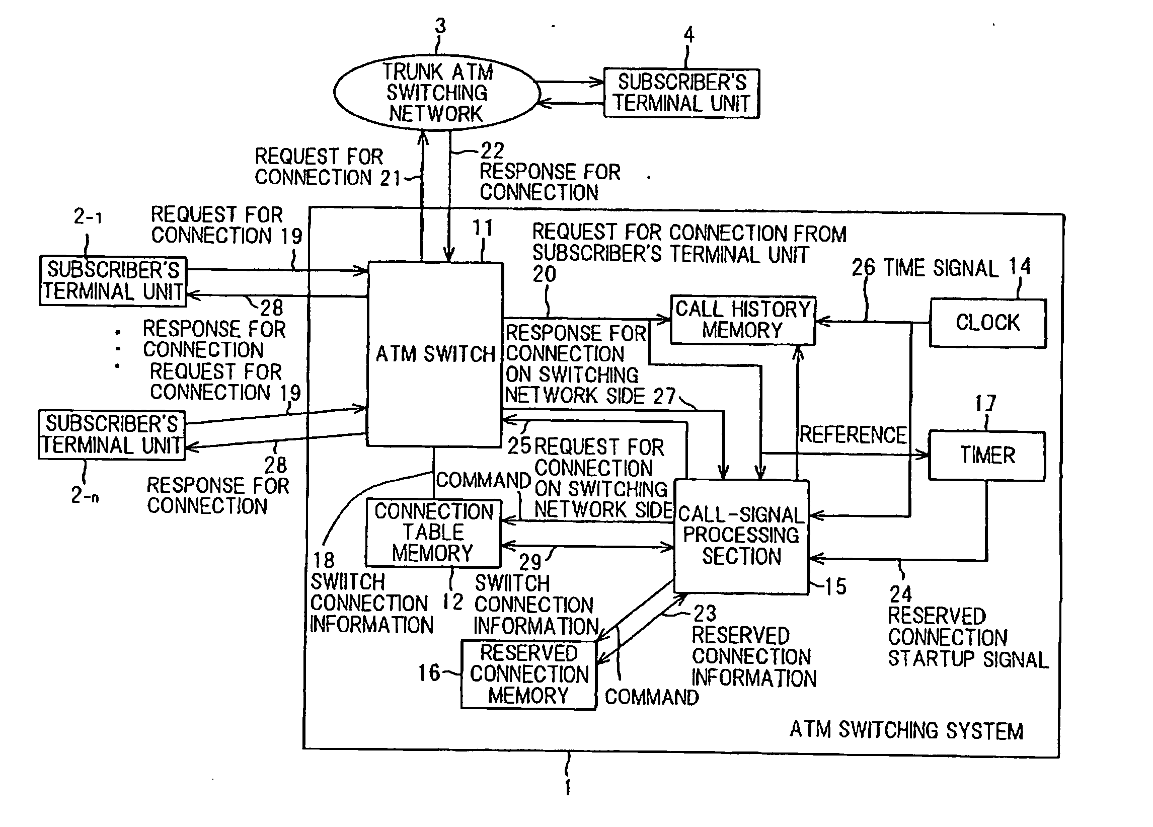
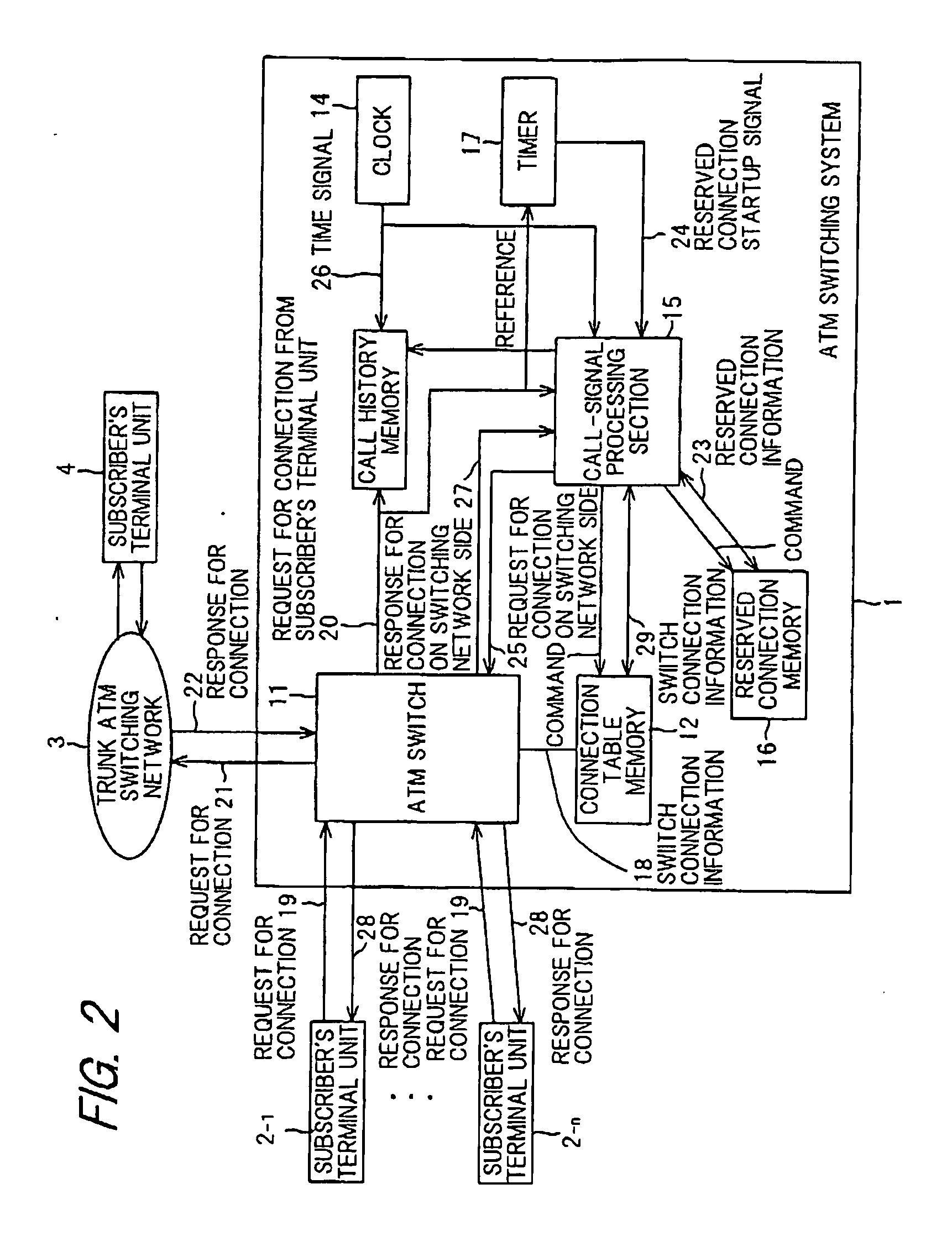
The present invention provides an ATM switching system that can handle a large number of calls simultaneously while reducing costs. The system includes a call history memory for maintaining call histories of requests for connection from subscriber's terminal units, a reserved connection memory for writing and reading reserved connection information, and a call-signal processing section. The section generates a request for connection based on the call histories and stores the response from the switching network as updated reserved connection information. This information is used to control the ATM switch in case of a call from any of the subscriber's terminal units. The system can prepare for the next call by comparing the contents of the request for connection with the response information, reducing the processing load and improving the response time.

Problems solved by technology

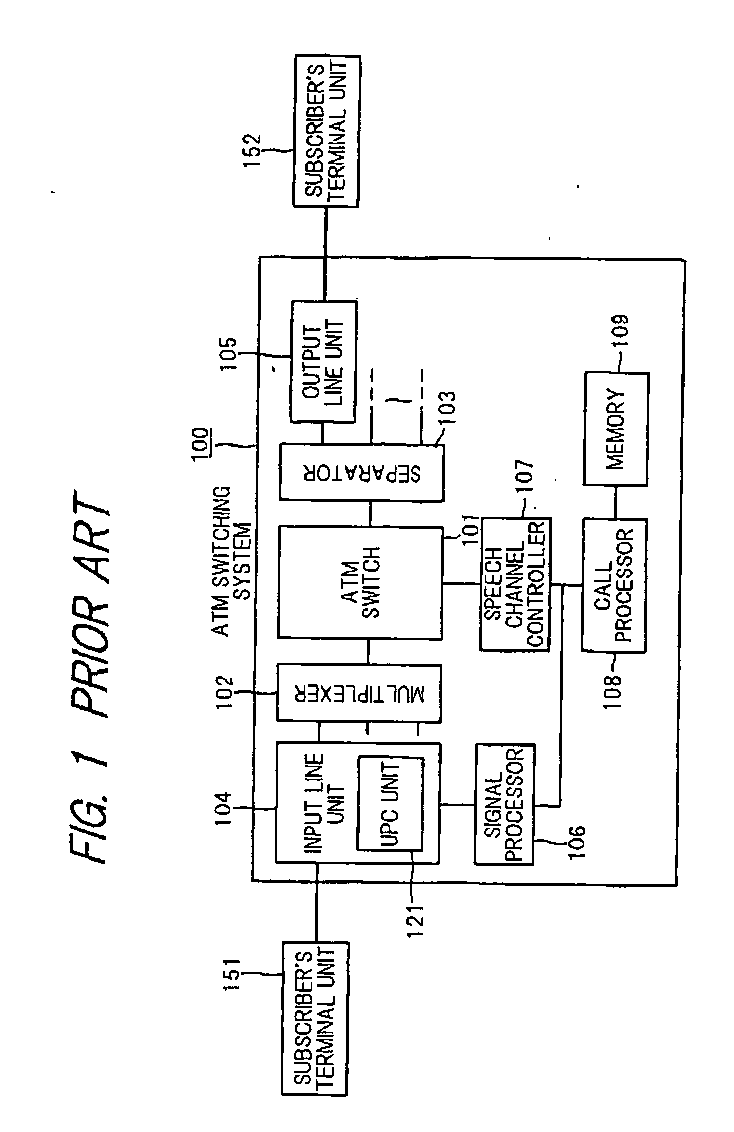
According to the conventional ATM switching system, however, the signal processor 106 and the call processor 108 are treated as a kind of components in the ATM switching system, a throughput capacity of them is suppressed to a certain level in view of hardware cost and average processing load, so that even if these processors are increased in the form of a plurality of pairs, there is a limitation as to the throughput capacity.
Moreover, there is such a high possibility that a calling subscriber calls again after lapse of a certain period of time in the case where the ATM switching system did not respond to a call made by the calling subscriber.
In an ATM switching system to which a large number of subscriber's terminal units have been connected, however, when it is intended to assure a desired processing speed even in case where all the subscriber's terminal units were called, an increase in cost due to an increase in a hardware scale cannot be avoided.

Method used


Image

  • Asynchronous transfer mode switching system
  • Asynchronous transfer mode switching system
  • Asynchronous transfer mode switching system

Examples


Embodiment Construction

[0022] Preferred embodiments of the present invention will be described hereinafter in conjunction with the accompanying drawings.

[0023]FIG. 2 is a block diagram showing an ATM switching system according to the present invention wherein subscriber's terminal units 2−1 to 2−n and a trunk ATM switching network 3 are connected to the ATM switching system 1, and a subscriber's terminal unit 4 has been connected to the trunk ATM switching network 3. The ATM switching system 1 is constituted with centering around an ATM switch 11, and a connection table memory 12 and a call history memory 13 are connected to the ATM switch 11. A call-signal processing section 15 is connected to the ATM switch 11, the connection table memory 12, and the call history memory 13, respectively. A clock 14 is connected to the call history memory 13, and a reserved connection memory 16 is connected to the call-signal processing section 15. Furthermore, a timer 17 is connected to the ATM switch 11 and the call-s...


PUM


Abstract

An ATM switching system 1 is provided with an ATM switch 11, a reserved connection memory 12 for storing reserved connection information, a call history memory 13 for maintaining call histories of requests for connection from subscriber's terminal units 2−1 to 2−n, and a call-signal processing section 15. The call-signal processing section 15 generates a request for connection with respect to a trunk ATM switching network 3 by the use of the call histories in the call history memory 13 in the case where no call was issued from the subscriber's terminal units, and stores response results thereof in the reserved connection memory 16. Thereafter, when there was a call from the subscriber's terminal units 2−1 to 2−n, and contents of the request for connection thereof are the same as the reserved connection information, which has been stored in the reserved connection memory 16, processing for connection is executed by the use of the reserved connection information. As a result, an ATM switching system by which response becomes possible in even the case where a large amount of calls are issued at the same time, besides reduction in cost can also be attained is provided.

Description

FIELD OF THE INVENTION [0001] The present invention relates to an ATM (Asynchronous Transfer Mode) switching system, and particularly to an ATM switching system that can perform ATM processing without delay in even a case where there are a number of calls at the same time. BACKGROUND OF THE INVENTION [0002] ATM has such a characteristic that switching processing wherein all of information are divided into a certain unit called by the name of “cell” a packet size of which is a fixed length (consisting of five byte header and forty-eight byte data), and so divided information is transferred asynchronously can be carried out by only a hardware. Accordingly, such switching processing is suitable for treating unitarily multimedia information. For instance, a frequency can be changed in response to contents of data in accordance with such a manner wherein cells are transferred thinly in case of E-mail, while cells are transferred densely in case of voice or moving image. Thus, there is su...

Claims


Application Information

Patent Timeline
Patent Type & Authority Applications(United States)
IPC IPC(8): H04L12/56H04L12/70
CPCH04L12/5601H04L49/253H04L47/10H04L2012/564H04L2012/563
Inventor SUZUKI, MAKOTO
Owner JUMIPER NETWORKS INC
Learn More